
Technical data


85108L System Manual
Operation
High Power Measurements
3-33
Measurement Example 2:
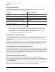
Figure 3-26 shows the setup for measurement of an amplifier with about 20 dB of gain that needs
an input level of about 40 dBm. A 40 dB gain amplifier is installed in the rear panel PORT 1 links to
boost the signal level to the desired value without exceeding +47 dBm (50 watts). The signal level at
the test port is about +60 dBm, making the signal levels at the a1 mixer and the b1 mixer over
+30 dBm.
In order to avoid damage:
• The ATTENUATOR PORT: 1 attenuator must be set to 30 dB in order to reduce the a1 and b1
signal levels to below −10 dBm.
• On the transmission return side, the amplifier output is about 60 dBm, making it necessary to
add 20 dB of loss between it and Port 2 in order to reduce the signal level incident at Port 2 to
less than +47 dBm.
• The ATTENUATOR PORT: 2 step attenuator must be set to 30 dB in order to protect the b2
mixer.
• The reverse pole of the forward/reverse switch must be protected by installing an attenuator or
isolator in the rear panel PORT 2 links to reduce the signal level at the reverse pole of the switch
to below +20 dBm.
The coupler is used in the transmission return signal path because it provides the necessary loss
and is likely to provide a more stable signal path than a high power attenuator that would
otherwise be required. A high power termination is required to terminate the through arm of the
coupler.
Figure 3-26 Measuring an Amplifier with High Input Levels