
Technical data


85108L System Manual
Operation
High Power Measurements
3-32
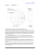
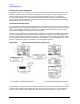
Measurement Example 1:
Figure 3-25 shows the setup for measurement of an amplifier having about 30 dB of gain. Using the
standard RF source power setting of +8 dBm, the signal level at Port 1 is about +0 dBm, the level at
the b2 mixer is about +4 dBm, and the signal level at the reverse pole of the forward/reverse switch
is about +30 dBm.
In order to avoid damage:
• The ATTENUATOR PORT: 2 step attenuator must be set to at least 20 dB to protect the b2
mixer.
• An attenuator or isolator must be added in the rear panel PORT 2 links to reduce the signal
level at the reverse pole of the switch to below +20 dBm.
• If any “IF OVERLOAD” message or O annotation is displayed on the network analyzer when you
are operating in the normal BW, nonpulsed-RF mode, the RF power level must be lowered until
the message no longer appears.
An isolator, providing about 30 dB of isolation between Port 2 and the switch, is the best choice
because it can preserve the dynamic range for reverse measurements. Better performance for the
reverse measurements will be obtained because the isolator will minimize the insertion loss from
the reverse pole of the switch to Port 2, and to a2.
NOTE The network analyzer cannot sense IF Overload conditions in the pulsed-RF, wide
BW mode of operation. Always check the user 1 through user 4 levels to be sure they
are below −10 dB indicated on the display.
Figure 3-25 Measuring a 30 dB Gain Amplifier