
Technical data


85108L System Manual
Operation
High Power Measurements
3-31
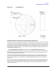
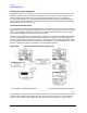
Figure 3-24 Test Set Maximum Signal Levels
Connecting External Signal Conditioning
The test set rear panel links labeled PORT 1 and PORT 2 can be used to install external equipment
in the Port 1 and Port 2 signal paths. The connectors labeled LOW POWER OUT each connect to an
output of the forward/reverse switch. The connectors labeled HIGH POWER IN connect to the front
panel measurement PORT 1 or PORT 2.
Note the damage levels indicated on the diagram. The maximum power rating of the
forward/reverse switch is +20 dBm applied at the RF input, or applied to the forward/reverse poles
via either LOW POWER OUT connector. The maximum signal level applied at either HIGH
POWER IN connector, or to either of the front panel PORT 1 and PORT 2 connectors is +47 dBm.
Example High Power Measurements
To set signal levels in the test set, estimate the input and output power levels of the device under
test. When the test set is configured to handle these levels, connect the operating device and verify
the power estimates by measuring the user parameters. If the estimates were inaccurate, change
the test set configuration so that power levels at all points in the system are within limits. When
this is accomplished, remove the device, perform a measurement calibration, then install the device
and measure its S-parameters.
Examples of two high power measurements follow. These examples should be used as a guide for
considerations that are special to your test setup.