
Technical data


85108L System Manual
Operation
High Power Measurements
3-30
High Power Measurements
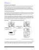
Use Figure 3-24 to examine the maximum power ratings and normal signal levels present in the
test set. The signal levels are approximate, with signal path loss increasing with frequency. Note
the following characteristics:
• Typically, the RF input is about 8 dBm and the loss to the selected test port is about 8 dB.
• With the step attenuators set to zero dB, the loss from the RF input to the a1 or the a2 mixer,
and the loss from Port 1 or Port 2 to the b1 or the b2 mixer, are approximately equal at about
26 dB.
• Since each mixer includes a 20 MHz preamplifier to offset its conversion loss, measurement of
the User Parameters will show the IF level to be about 24 dB less than the RF input and 16 dB
less than the signal level at the test port, with 0 dB test port attenuation.
• For specified performance, the maximum IF signal level as measured by the user parameters is
−10 dBm. Higher signal levels cause errors due to compression, and lower signal levels produce
greater uncertainty due to noise.
CAUTION Components in the test set will be damaged at certain signal levels. To avoid damage,
observe the following operating precautions:
1. Use the PORT 1 and PORT 2 attenuators (Stimulus Power menu) to protect the
mixer input — the mixer damage level is +20 dBm (0.1 watt, CW).
2. Install appropriate components in the rear panel extension links to protect the
test set Forward/Reverse switch — the damage level is +20 dBm applied at any
input or output. This means that if the device output is greater than +20 dBm, the
switch can be damaged by +20 dBm present at either LOW POWER OUT connector.
3. If the device output is greater than +47 dBm, use appropriate components to
protect the test set ports (and the Forward/Reverse switch) — the damage level is
+47 dBm (50 watts) applied at PORT 1 or PORT 2.