
Technical data


85108L System Manual
Operation
Pulsed-RF Applications
3-29
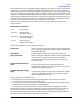
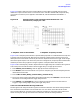
Figure 3-23 shows results using this pulse modulation and triggering method when the pulse
modulation input to the RF source is a continuous train of 20 microseconds PRP, 50 percent duty
cycle pulses. The same input is applied to TRIGGER IN, and TRIGGERING EXTERNAL is
selected.
Figure 3-23 Using External Trigger and External Modulation PRP = 20
microseconds, Duty Cycle = 50%
Figure 3-23a is the pulse profile domain response. Multiple pulses are visible because the stop time
is greater than the stimulus PRP. Notice that for external triggering the minimum start time is
about positive 3 measurement resolution periods with respect to the external trigger. Even though
the internal pulse output is not used in this particular configuration, the pulse profile measurement
resolution period is set by algorithm using the greater of the pulse width and stop time.
Figure 3-23b is the frequency domain response with the trigger delay set to measure during the On
time of the pulse. One method used to set the trigger delay to an appropriate value is:
1. Press
DOMAIN, [PULSE PROFILE], then set appropriate Start and Stop times.
2. Press
MARKER, then move the marker to the point on the pulse you want the frequency domain
measurement to be made.
3. Press
STIMULUS MENU, [MORE], [TRIGGER MODE], [TRIGGER DELAY].
4. The current value of the Trigger Delay will be displayed. Now press
=MARKER. The time value at
the marker will be assigned to the trigger delay function.
5. Press
DOMAIN, then [FREQUENCY]. The trace shows the response at the time after the TTL
Trigger In signal falling edge as set by the trigger delay value.
Control of Pulse Modulation During Calibration
The RF signal must always be On during the time that the calibration standard is being measured.
This removes the time element from the calibration. For this reason, either disconnect the RF
source pulse modulation input during the calibration procedure or take other step to ensure that
the RF is always On during the time that the calibration standard is being measured.
a. Amplifier Pulse Profile Domain b. Amplifier Frequency Domain