
Technical data


85108L System Manual
Operation
Pulsed-RF Applications
3-28
Using External Pulse Modulation
In applications where it is necessary to maintain close control over the PRP and duty cycle of the
pulsed-RF stimulus, you can use external equipment to provide the TTL pulse modulation and
external trigger signals. When using an external pulse modulation signal, it is necessary to
synchronize the network analyzer with the pulse modulation signal so that the measurement is
always made at the same time with respect to the stimulus. This synchronization is accomplished
using the 8510 external trigger input.
Connect the Pulse Generator
A simple method to control the PRP and duty cycle of the pulsed-RF stimulus is to use an external
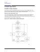
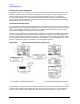
pulse generator to provide the pulse modulation input to the RF source. Figure 3-22 shows a simple
setup. In this example, the same TTL pulse train provides the pulse modulation input to the RF
source and to the 8510 rear panel TRIGGER IN connector.
However, in your application it may be desirable to use different synchronized inputs to the network
analyzer TRIGGER IN and to the source pulse modulator. If an 8340 source is used, please note
that for internal triggering, a BNC short circuit is connected to the TRIGGER IN connector. When
the pulse generator is connected to TRIGGER IN, move the BNC short to the SWEEP IN 0 to 10V
connector. Otherwise, signals on the sweep in line could affect triggering.
Figure 3-22 External Control of PRP and Duty Cycle
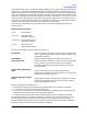
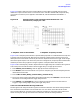
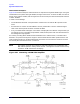
Synchronization is assured because time equals zero seconds for each measurement cycle is defined
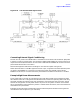
as the first falling edge of the trigger input after stop sweep is ready (high). Figure 3-22b shows
connection of an external pulse modulator instead of the internal modulator in the RF source.