
Technical data


85108L System Manual
Operation
Pulsed-RF Applications
3-27
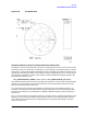
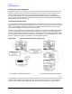
If you are viewing this with an oscilloscope, notice how the measurement cycle time varies
according to the pulse profile stop time. If the stop time is greater than the pulse width, the
measurement cycle time will extend past the end of the pulse depending on the time value of the
data point being measured. Depending on the pulse width, this can result in a lower percent duty
cycle toward the end of the time span.
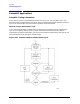
External Trigger and Stop Sweep Signals
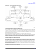
Figure 3-21 shows the relationship between the external Trigger Input and the 8510 Stop Sweep
output for frequency domain point-in-pulse measurements and for pulse profile domain
measurements. For external triggering, Stop Sweep remains Busy (low) until the measurement
cycle is complete. This information is important for synchronizing the pulse modulation to the
external trigger.
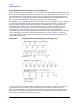
When a TTL pulse train is applied to the 8510 rear panel EXTERNAL TRIGGER INPUT, the
trigger should stay low for at least 100 nanoseconds. Excess triggers that occur while stop sweep is
busy (low) are ignored. The next external trigger falling edge after stop sweep is ready will initiate
the next measurement cycle and retrace is automatic.
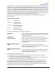
Figure 3-21 External Trigger and Stop Sweep Timing Diagram
When internal triggering is selected, the stop sweep output does not operate (always in the ready
state). Timing diagrams for the pulse output signal and development of the internal measurement
trigger are shown in Figure 3-11 on page 3-14 and Figure 3-12 on page 3-15.
When external triggering is selected, the falling edge of the external trigger input defines time
equals zero seconds for each measurement cycle. Stop sweep falls immediately and stays low until
the 8510 completes the measurement cycle and is ready to accept the next trigger. The time period
that stop sweep remains busy depends upon the next measurement function to be performed. Pulse
output is turned Off for external triggering. As for internal triggering, the pulse profile
measurement resolution period is set by the larger of pulse width and pulse profile domain stop
time.