
Technical data


85108L System Manual
Operation
Pulsed-RF Applications
3-26
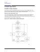
Pulse Repetition Period and Duty Cycle Considerations
From the measurement cycle information, you can see that the pulse repetition period and thus the
duty cycle of the pulsed-RF signal applied to the DUT can vary depending on the instrument state.
For measurements in which the PRP or duty cycle is not important, set the pulse width and the
duty cycle controls to an appropriate value and make the measurement. The specified duty cycle
limit will not be exceeded, but the actual duty cycle may be less than expected.
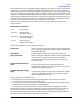
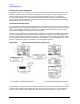
For example, Figure 3-20 shows the pulse output waveform for various conditions. Figure 3-20 part
“a” shows the pulse output when the pulse width is 500 microseconds, the duty cycle limit is 50
percent, and averaging is off. Under these conditions the measurement cycle time is about 3
milliseconds per trace data point in the pulse profile domain, or about 30 milliseconds in the
frequency domain. Figure 3-20 part “b” shows the same conditions with averaging on and an
averaging factor of four. Now four measurements are taken for each data point with the
measurement cycle time alternating between 1 millisecond for each of the measurements required
for the averaging, and the time to move to the next data point. Figure 3-20 part “c” shows the
measurement when 2-Port correction is On. Here, the parameter switching time also affects the
overall PRP and duty cycle.
Figure 3-20 Example Internal Pulse Output PRP and Duty Cycle
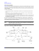
In Figure 3-20 part “d,” the pulse width is greater than the measurement cycle time, so the duty
cycle could approach 100 percent. This is avoided by setting the Duty Cycle function to the
maximum value allowed in the measurement. When the combination of the pulse width and the
duty cycle limit approaches the measurement cycle time, the pulse off part of the measurement
cycle time is increased to satisfy the duty cycle limit.