
Technical data

85108L System Manual
Operation
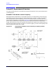
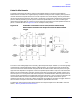
Pulsed-RF Measurements Overview
3-22
4. Set Measurement Time Span. The 8510 automatically chooses the minimum possible time
between samples (given the 8510 hardware and firmware capabilities), and thus the
measurement resolution period, depending on the larger of the pulse width time or the stop time.
This results in a minimum possible span time which depends on the current number of points.
To view the pulse with minimum sample resolution period and thus the best time resolution,
press
STIMULUS STOP, then repeatedly press the entry STEP Down key until the time value at
the bottom of the grid does not change (or enter
STOP, 0, x1). This also sets the start time to the
minimum value. If the pulse is longer than this time span, increase the stop time to view the
entire time period of interest.
5. Set Measurement Resolution Period. To find the resolution period, press
MARKER, then
move the marker one data point and see the time change in the Active Entry area. If necessary,
adjust the resolution period to the value required for your measurement by changing the stop
time, pulse width, and number of points.
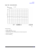
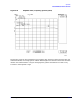
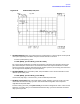
Figure 3-17 Minimum Time Span, Resolution Period = 100 ns
6. Connect the Device under Test. With the pulse width set, connect the device under test. The
trace will show the response of the device to the pulsed-RF stimulus at the current frequency.
7. To measure another frequency, recall the appropriate cal set (for pulse profile domain
calibration) or frequency list segment (for frequency list calibration).
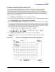
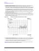
Figure 3-18 shows the S11 response using the Smith chart format. The marker shows the input
impedance during the On time of the pulsed-RF stimulus.