
Technical data

85108L System Manual
Operation
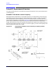
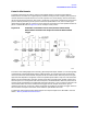
Pulsed-RF Measurements Overview
3-21
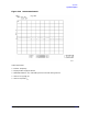
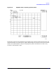
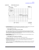
Figure 3-16 Pulse Profile, S21, Thru
1. Set Pulse Polarity. After instrument preset, the pulse polarity is set to High for the On period
of the pulse appearing at the 8510 rear panel PULSE OUTPUT connector.
To set the pulse polarity, press:
SYSTEM, [MORE], [PULSE CONFIG], [PULSE OUT: HIGH].
For internal pulse modulation and internal triggering, time equals zero seconds is always the
point where the pulse transitions to the active level. The internal pulse modulator in the RF
source turns the RF pulse On when the analyzer output is positive, so the noisy part of the trace
will change location depending on the pulse polarity.
2. Set Pulse Width. After instrument preset, the pulse width is set to 10 microseconds. To set a
different pulse width press:
SYSTEM, [MORE], [PULSE CONFIG], [PULSE WIDTH].
Use the knob, step keys, or numeric entry to set the desired pulse width.
3. Set Duty Cycle Limit. After instrument factory preset, the duty cycle limit is set to 10. This
means that the maximum duty cycle will never be allowed to be greater than 10 percent
regardless of the pulse width.
To set the duty cycle limit, press
[DUTY CYCLE] on the Pulse Configuration menu. Use the knob,
step keys, or numeric entry to set the desired maximum duty cycle limit. Note that the actual
duty cycle may be less.