
Technical data

85108L System Manual
Operation
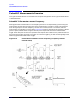
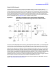
Pulsed-RF Measurements Overview
3-16
Making Pulsed-RF Measurements
Frequency Domain (Point-In-Pulse)
Calibration
Measurement calibration for frequency domain (point-in-pulse) is accomplished in exactly the same
way as for the standard 8510 network analyzer.
1. Press
DOMAIN, then [FREQUENCY] to select the frequency domain.
2. If the W annotation is not displayed, select the wideband detector by pressing:
SYSTEM, [MORE],
[PULSE CONFIG], [DETECTOR: WIDE BW]
.
3. Select the maximum number of points required for the measurement, then perform the
appropriate measurement calibration.
Note that for internal triggering, when you press the key to measure the calibration standard, the
8510 pulse output signal is set to the active state (RF always On) during measurement of the
standard. This assures that the calibration is made with respect to the On portion of the pulse
independent of the trigger delay.
Note that for external triggering you can control the pulse width and duty cycle during calibration
and measurement. You must set the trigger delay to make the measurement at the correct time
during the pulse for calibration, then not change it during the measurement.
Measurement
1. Set Pulse Polarity. After factory preset, the pulse polarity is set to High for the On period of
the pulse appearing at the 8510 rear panel PULSE OUTPUT connector. To set the pulse polarity,
press:
SYSTEM, [MORE], [PULSE CONFIG], [PULSE OUT: HIGH].
2. Set Pulse Width. After factory preset, the pulse width is set to 10 microseconds. To set a
different pulse width:
Press
[PULSE WIDTH]. Use the knob, step keys, or numeric entry to set the desired pulse width.
3. Set Duty Cycle Limit. After factory preset, the duty cycle limit is set to 10. This means that
the maximum duty cycle will never be allowed to be greater than 10 percent regardless of the
pulse width.
To set the duty cycle limit, press
[DUTY CYCLE] on the Pulse Configuration menu. Use the knob,
step keys, or numeric entry to set the desired maximum duty cycle limit. Note that the actual
duty cycle may be less.
4. Set Trigger Delay. After a factory Preset, the trigger delay is set to 5 microseconds. This means
that the frequency domain measurement will take place 5 microseconds after time zero. Time
equals zero seconds when the 8510 pulse output goes to the active level turning on the pulse
modulator. To set the trigger delay, press
STIMULUS MENU, [MORE], [TRIGGER MODE],
[TRIGGER DELAY]
. Use the knob, step keys, or numeric entry to set the desired trigger delay.
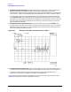
Notice that if the trigger delay is set to outside the time interval that the pulse is On, the trace is
noisy due to low signal levels.
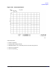
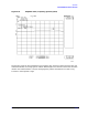
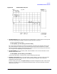
5. Connect the Device Under Test. The trace shows the response of the device to the pulsed-RF
stimulus over the current frequency sweep
Figure 3-13 shows an example of amplifier gain.