
Technical data

85108L System Manual
Operation
System Description
3-2
System Description
Pulsed-RF stimulus and response measurements may be required in cases where continuous
application of a test signal could destroy a device under test, such as when testing occurs prior to
packaging, or where a device must be tested using a PRF (pulse repetition frequency) and duty cycle
that accurately represents its final application.
The pulsed-RF network analyzer system:
• adds specialized hardware and an optimized firmware feature set to make fully error-corrected
S-parameter measurements of pulsed-RF responses.
• combines wideband IF and accurate timing circuits to provide precise synchronization with the
pulse, which allows S-parameters to be measured at a precisely known, repeatable time during
the pulse.
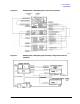
A simplified block diagram of the system is shown in Figure 3-1. One synthesizer provides the test
signal stimulus to the RF input of the test set and the other provides the LO signal to the four
frequency converters (only two are shown). The LO source is always tuned 20 MHz above the test
signal source. Instead of the standard internal phaselock technique, a common 10 MHz frequency
reference is used for both of the sources and the internal sample selection and timing logic in the
network analyzer. These sources are considered to be coherent, thus generating the correct 20 MHz
first IF and the correct clock frequency for the reference and test synchronous detectors. This
eliminates the need to use the reference signal for receiver phaselock and allows all reference and
test signals to be pulsed, thereby making fully error-corrected 2-port, pulsed-RF S-parameter
measurements possible.
One pulse of a user-specified width is measured at each data point and the measurement is
synchronized so that it is made at a certain known time in the pulse. The stimulus duty cycle can be
predicted for a given instrument state, but the actual pulse repetition period depends on the current
domain, cal type, averaging, sweep time, and pulse width selections. For this reason, if your device
is sensitive to duty cycle, refer to “Pulsed-RF Timing Information” on page 3-24.
Either the internal logic, the TTL Trigger Input, or the GPIB Group Execute Trigger from an
external computer can initiate a measurement cycle. When control of the pulse repetition period
and duty cycle is required, the network analyzer can use the trigger input to synchronize with the
internal or an external pulse modulator. The 8510 Stop Sweep output can be used as a gating signal
to tell when the analyzer is ready for the next measurement. The measurement is made with 100
nanosecond resolution, and about 200 picosecond uncertainty with respect to the internally- or
externally-generated measurement trigger.
CAUTION During the retrace time of the network analyzer, the source power may remain on.