
Technical data

85108L System Manual
System Installation
System Arrival
2-14
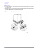
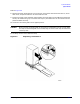
Connecting a Plotter
To connect a plotter to the system, connect one end of the GPIB cable to the plotter (the plotter
should have its own GPIB cable). Connect the “free” end of the plotter cable to either the 8510
Interconnect connector (for system bus control) or to the GPIB connector (for GPIB bus control).
Refer to “Making Connections” on page 2-12 for more information regarding the busses. Set the
plotter GPIB address to 5.
Connect the plotter to an ac power source and turn it on. Refer to the next section, “Accessory ac
Power Outlet,” for information about connecting the plotter to an ac power outlet inside the system
cabinet.
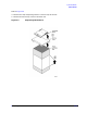
Accessory ac Power Outlet
All power connections for instruments in the system are located inside the cabinet via a
multiple-outlet power strip. On some systems, an extra power outlet is provided on the power strip
for accessories. Special “boot” ac power cables are included with your 85108L system for this
purpose.
CAUTION Before connecting any equipment to the extra power outlet, refer to Table 2-2,
“Maximum VA Ratings and BTU/hour Ratings of Instruments,” on page 2-6 for the
maximum VA ratings for this outlet on your system.
85108L Installed in a Different Cabinet
Agilent strongly recommends that the 85108L system cabinet be used with the 85108L pulsed-RF
system. Agilent is not obligated to support user-configured pulsed-RF rack systems other than the
85108L rack-mounted system. The customer takes full responsibility for instrument damage
incurred due to using racks or system cabinets other than the one supplied with the 85108L system.
See “Contacting Agilent” on page iv to order a rack for your system.
System Turn On
Check the fuses of each instrument and verify that they match the local line voltage. Refer to the
individual instrument manual to change the fuse or the fuse setting.
Turn On System Power
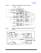
1. Verify that all cables are connected properly (refer to Figure 2-6 or Figure 2-7).
2. Turn on power to the system rack and to all instruments except the 8510 network analyzer.
3. Once all the instruments are on, turn on the 8510.
Verify GPIB Addresses
Verify that the instrument addresses are set correctly after system power on. On the network
analyzer, press:
SYSTEM [HP-IB ADDRESSES].
Press the softkey that corresponds to each instrument in your system to check each address. Press
[MORE] to show additional instrument choices.
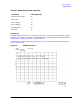
Compare the addresses on the network analyzer display with the addresses listed in Table 2-3. To
change an address, press the softkey corresponding to the desired instrument, then enter the
correct address from the keypad:
[n] [n] [x1].