
Technical data

85108L System Manual
System Installation
System Arrival
2-12
System and Benchtop Configuration and Cabling
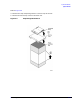
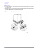
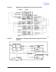
The configuration of the rack-mounted system with cabling is shown in Figure 2-6. The suggested
configuration of the benchtop system with cabling connections is shown in Figure 2-7.
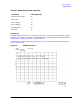
You can configure your own pulsed-RF system using instruments you may already own. The
pulsed-RF system consists of the following instruments:
The RF source must be capable of pulsed operation over the frequency range of 45 MHz to 2 GHz.
The LO source must be capable of +10 dB levelled output over the frequency range of 45 MHz to
2GHz.
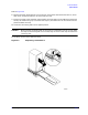
Installing a Computer
A computer must be connected to your system to run the performance verification software. The
computer must be an HP 9000 series 300 computer with BASIC 5.0 or later and there must be two
megabytes of available RAM after BASIC has been loaded. Refer to Chapter 4, “Specifications and
Performance Verification,” for more information.
Making Connections
There are two separate buses in this system:
•The GPIB bus
• The 8510 system bus
Both buses use the same type of connector and cable, but the buses are not interchangeable.
The GPIB Bus
The computer retains full control of this bus; no other device can send commands unless the
computer relinquishes control. Connect your peripheral equipment to this bus only if you want this
equipment to be controlled by the computer.
The 8510 System Bus
The 8510 must be able to send GPIB commands to the other instruments in the system at any time,
without waiting for “permission” from the computer. To facilitate this, a special GPIB bus was
created called the 8510 System Bus. Connect your peripheral equipment to this bus (via the “8510
Interconnect” connector) only if you want this equipment to be controlled by the 8510.
Quantity Item
1 8510C Option 008 network analyzer
1 85110L S-parameter test set
1 Agilent source (RF)
1 Agilent source (LO)