
Technical data


B-4 85108L System Manual
Hardware and Instrument States
Examining Your Pulse Hardware and Instrument State
Examining Your Pulse Hardware and Instrument State
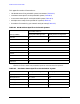
Use the following key sequence to examine the hardware and instrument states residing in
your network analyzer. These are the settings for the pulsed-RF configuration file on the
85108L system configuration disk (refer to Appendix C, “Loading the System
Configuration Disk”).
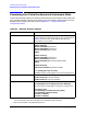
Table B-5 Network Analyzer Settings
To Check Analyzer Settings Press These Keys on the Network Analyzer
GPIB Addresses
SYSTEM [HP-IB ADDRESS]
Press the softkey of each instrument in your system. Refer to
Table B-1 for the correct GPIB address settings of the
instruments in your system.
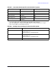
Multiple Source
SYSTEM [MORE] [EDIT MULT. SRC.]
[DEFINE SOURCE 1]
[MULTIPLIER NUMER.]
should be 1.
[MULTIPLIER DENOM.] should be 1.
[OFFSET FREQUENCY] should be 0.
[DONE]
[DEFINE SOURCE 2]
[MULTIPLIER NUMER.]
should be 1.
[MULTIPLIER DENOM.] should be 1.
[OFFSET FREQUENCY] should be 20.000017 MHz.
[DONE]
[DEFINE RECEIVER]
[CONSTANT FREQUENCY]
should be 20 MHz.
Press
[DONE] [MULT.SRC: ON /SAVE].
(An M annotation should appear to the left of the graticule.)
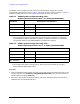
Power Source STIMULUS MENU [POWER MENU]
[POWER SOURCE1]
should be +8 dBm.
a
[POWER SOURCE 2] should be +10 dBm.
a. Set source 1 power to the highest level possible without IF overload. Power must be set in
the “normal BW” mode, then changed to the “wide BW” mode, if desired.
Sweep Mode
STIMULUS MENU [STEP]
SYSTEM [MORE] [PULSE CONFIG] [DETECTOR: WIDE BW]
b
(A W annotation should appear to the left of the graticule.)
[PULSE OUT: HIGH]
SYSTEM [MORE] [SYSTEM PHASELOCK] [NONE]
SYSTEM [MORE] [POWER LEVELING]
[SOURCE1: INTERNAL]
[SOURCE2: INTERNAL]
b. Set to normal BW for nonpulsed-RF operation.