
Technical data


B-2 85108L System Manual
Hardware and Instrument States
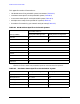
This appendix contains information on:
• GPIB addresses of the pulsed-RF system instruments (Table B-1).
• Hardware states specific to the pulsed-RF system (Table B-2).
• Instrument states specific to the pulsed-RF system (Table B-3).
• Multiple source setup for the pulsed-RF system (Table B-4).
• Procedures for examining your network analyzer setup (Table B-5).
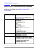
Table B-1 GPIB Address Specific to Pulse-RF Systems
8510 System Bus
System Bus Addresses
During Pulsed-RF Operation During 2nd Test Set Operation
Test set 20 21
RF switch 31
28
a
a. If you have Option 001 in your test set and a second test set connected, the RF switch
address can be left a 28 for both pulsed-RF operation and second test set operation.
Address of 8510 16
System bus 17
Source #1 (RF) 19
Source #2 (LO) 18
Plotter 5
Printer 1
Disk 0
Pass-thru 31
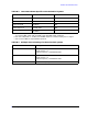
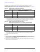
Table B-2 Hardware States Specific to the Pulsed-RF System
System Parameter During Pulsed-RF Operation During Operation of 2nd Test Set
System phaselock None Internal
Multiple source On / Save Off
Leveling source #1 Internal Internal
Leveling source #2 Internal N/A
Sweep mode STEP or FRQ LIST Any