
Technical data


85108L System Manual
System Service and Troubleshooting
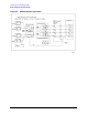
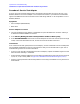
85108 IF/Detector Option 008 Pulsed-RF IF Path Troubleshooting Flowchart
6-18
Procedure 5: A6 Clock 20 MHz Output Check
1. Disconnect the cable W5 or W54 at A6J9 or J8 and connect an oscilloscope to A6J8 or J9.
The output should typically be about 1.8 volts peak to peak into the 1 MOhm oscilloscope input
impedance. The output voltage drops to about 1.2 volts peak-to-peak when connected to the
pulse detector via W5 or W54.
A6J7 connects to the 20 MHz output on the rear panel and provides the same signal level.
2. If the signal is missing or greatly differs between J8, J9, and J7, replace the A6 Clock board.