Agilent Technologies 85108L Pulsed-RF Network Analyzer System System Manual Serial Numbers This manual applies directly to instruments with serial prefix number 3110A or above. Firmware This manual applies directly to all 8510 instruments that have been upgraded to the 8510C, with operating firmware revision 6.50 or higher.
Notice The information contained in this document is subject to change without notice. Agilent Technologies makes no warranty of any kind with regard to this material, including, but not limited to, the implied warranties of merchantability and fitness for a particular purpose. Agilent Technologies shall not be liable for errors contained herein or for incidental or consequential damages in connection with the furnishing, performance, or use of this material.
Safety and Regulatory Information Review this product and related documentation to familiarize yourself with safety markings and instructions before you operate the instrument. This product has been designed and tested in accordance with international standards. WARNING The WARNING notice denotes a hazard. It calls attention to a procedure, practice, or the like, that, if not correctly performed or adhered to, could result in personal injury.
Safety Earth Ground This is a Safety Class I product (provided with a protective earthing terminal). An uninterruptible safety earth ground must be provided from the main power source to the product input wiring terminals, power cord, or supplied power cord set. Whenever it is likely that the protection has been impaired, the product must be made inoperative and secured against any unintended operation.
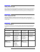
Typeface Conventions Italics • Used to emphasize important information: Use this software only with the Agilent Technologies xxxxxX system. • Used for the title of a publication: Refer to the Agilent Technologies xxxxxX System-Level User’s Guide. • Used to indicate a variable: Type LOAD BIN filename. Instrument Display • Used to show on-screen prompts and messages that you will see on the display of an instrument: The Agilent Technologies xxxxxX will display the message CAL1 SAVED.
vi
Contents 1. System and Documentation Overview Manual Overview . . . . . . . . . . . . . . . . . . . . . . . . . . . . . . . . . . . . . . . . . . . . . . . . . . . . . . . . . . . .1-2 Where to Find Information. . . . . . . . . . . . . . . . . . . . . . . . . . . . . . . . . . . . . . . . . . . . . . . . . . .1-2 System Overview. . . . . . . . . . . . . . . . . . . . . . . . . . . . . . . . . . . . . . . . . . . . . . . . . . . . . . . . . . .1-4 Systems Covered by This Manual . . . . . . . . . . . . . . .
Contents 4. Specifications and Performance Verification Overview . . . . . . . . . . . . . . . . . . . . . . . . . . . . . . . . . . . . . . . . . . . . . . . . . . . . . . . . . . . . . . . . . . 4-2 Required Equipment . . . . . . . . . . . . . . . . . . . . . . . . . . . . . . . . . . . . . . . . . . . . . . . . . . . . . . . 4-4 Verifying Non-Standard Systems . . . . . . . . . . . . . . . . . . . . . . . . . . . . . . . . . . . . . . . . . . . . . 4-4 Recommended Performance Verification Cycle . . . . .
1 System and Documentation Overview 85108L System Manual 1- 1
System and Documentation Overview Manual Overview Manual Overview Use this manual for installation, operation, calibration, performance verification, and troubleshooting of the pulsed-RF network analyzer system. Consult the manuals of the individual instruments and accessories in the system when necessary for reference. The 85108 system, shown in Figure 1-1, is a factory integrated pulsed-RF system which includes the following components.
System and Documentation Overview Manual Overview Figure 1-1 Typical 85108L Pulsed-RF Network Analyzer System 85108L System Manual 1- 3
System and Documentation Overview Manual Overview System Overview The pulsed-RF network analyzer system allows you to measure and display the relative magnitude and phase shift of the component under test as a function of time with an equivalent bandwidth of 1.5 MHz. You can evaluate dynamic pulsed-RF characteristics for pulse widths down to 1 microsecond.
2 System Installation 85108L System Manual 2- 1
System Installation System Arrival System Arrival The pulsed-RF network analyzer system will be rack-mounted, assembled, and with the cabling attached when it arrives from the factory. Keep the shipping containers in one area to help verify the receipt of all components ordered. Inspect all shipping containers. Keep the carton and packaging material until the entire shipment has been verified for completeness, and the system has been checked mechanically and electrically.
System Installation System Arrival Table 2-1 System Equipment Checklist 85108L Standard System Instrument Manual/Software Part Number 8510C network analyzer (Option 008) 08510-90275 85110L S-parameter test set 85110-90048 83620B-H80 Synthesized Sweeper (RF) (with Options 001, 004, and 008) 83620-90007 83620B-H80 Synthesized Sweeper (LO) (with Options 004 and 008) Software 8510 Specifications and Performance Verification software (Revision A.05.01 or higher) 08510-10033 85108L for use with 8510C.
System Installation System Arrival Figure 2-1 2-4 85108L Pulsed-RF Network Analyzer System 85108L System Manual
System Installation System Arrival Site Preparation Site preparation includes the environmental and electrical requirements necessary for the 85108 system to operate within its specifications. Make sure your site meets these requirements before installing the system. 85108L Environmental Requirements The environmental requirements of the 85108 system are given below. These characteristics are the same as those for the 8510C network analyzer.
System Installation System Arrival Table 2-2 Maximum VA Ratings and BTU/hour Ratings of Instruments1 Instrument Maximum VA Rating VA Subtotal Maximum BTU/hour BTU/hour Subtotal Standard Equipment 85101 display/processor 250 _________ 850 _________ 85102 IF/detector 210 _________ 714 _________ 85110A test set 110 _________ 323 _________ 8360 series synthesized source 400 _________ 1,360 _________ 8360 series synthesized source 400 _________ 1,360 _________ 1355VA _________ 46
System Installation System Arrival System Voltages All instruments in the 85108 system must be set to the local voltage. All system instruments are set to 120 Vac at the factory, except for Option 230 systems, which are set to 220 Vac. CAUTION The cabinet fans may be permanently damaged if a 120V system is plugged into a 230V ac power outlet. The cabinet fans are wired for either 120V or 230V, but not both.
System Installation System Arrival Unpacking the System Cabinet The lifting brackets supplied with the rack are suitable for lifting the rack fully loaded. CAUTION Do not lift the rack (unpacked) with a fork lift. Use the following procedure to remove the rack from the shipping base. This procedure can be performed by one person. CAUTION Wear protective glasses while cutting the plastic bands around the shipping container. These bands are under tension.
System Installation System Arrival Refer to Figure 2-3. 4. Remove the ramp and packing material ① from the top of the rack. 5. Remove the shrink-wrap ② from around the rack.
System Installation System Arrival Refer to Figure 2-4. 6. Carefully open the rear door ①. Remove the screw holding the rear door-support ② in place and pull the block out. 7. Remove the two (on each side) shipping clamps from the bottom of the frame. They are bolted to the pallet. Remove the bolt ③ and then remove the clamp ④.
System Installation System Arrival Refer to Figure 2-5. 8. Remove the pallet shipping block ② from the rear of the pallet. Remove the two bolts ①, one on each corner, and pull the block ② out from under the rack. 9. Position the ramp so that the block of wood under the ramp loads into the edge of the pallet with the strip of wood forming a lip. This holds the ramp in place while the rack is moved across the pallet and down the ramp. 10. Raise the rack leveling feet to their highest position.
System Installation System Arrival System and Benchtop Configuration and Cabling The configuration of the rack-mounted system with cabling is shown in Figure 2-6. The suggested configuration of the benchtop system with cabling connections is shown in Figure 2-7. You can configure your own pulsed-RF system using instruments you may already own.
System Installation System Arrival Figure 2-6 85108 System Cabling Diagram (rack mounted system) Figure 2-7 85108 System Cabling Diagram (benchtop configuration-without amplifier) 85108L System Manual 2- 13
System Installation System Arrival Connecting a Plotter To connect a plotter to the system, connect one end of the GPIB cable to the plotter (the plotter should have its own GPIB cable). Connect the “free” end of the plotter cable to either the 8510 Interconnect connector (for system bus control) or to the GPIB connector (for GPIB bus control). Refer to “Making Connections” on page 2-12 for more information regarding the busses. Set the plotter GPIB address to 5.
System Installation System Arrival Table 2-3 85108 System GPIB Addresses Instrument GPIB Addresses 8510 network analyzer 16 System bus 17 Source #1 (RF) 19 Source #2 (LO) 18 Test set: 85110 20 RF switch 31 Initial Trace Once the system is turned on, you should see a trace similar to Figure 2-8 on the network analyzer display. If your display is not similar, load the 85108 system configuration disk using the procedure in Appendix C, “Loading the System Configuration Disk.
System Installation System Arrival Firmware Revision All properly functioning systems display the firmware revision information illustrated in Figure 2-8 after system turn on. • 8510C-based systems must have firmware revision 8510C.06.50 or greater. • 8510B-based systems must have firmware revision 8510B.05.11 or greater. If your 8510B has firmware revision 8510B.06.
3 Operation 85108L System Manual 3- 1
Operation System Description System Description Pulsed-RF stimulus and response measurements may be required in cases where continuous application of a test signal could destroy a device under test, such as when testing occurs prior to packaging, or where a device must be tested using a PRF (pulse repetition frequency) and duty cycle that accurately represents its final application.
Operation System Description Figure 3-1 Simplified Pulsed-RF Network Analyzer Block Diagram 85108L System Manual 3- 3
Operation System Description 85110L S-Parameter Test Set Operation Figure 3-2 shows a detailed diagram of the 85110L test set signal separation, signal routing, and frequency conversion. This is a fundamentally mixed test set, providing four 20 MHz outputs to the 8510. Placement of a 0 to 70 dB (10 dB/step) attenuator before each mixer provides control of the signal levels into the mixers while allowing operation at high PORT 1 and PORT 2 signal levels necessary in many pulsed-RF applications.
Operation System Description Controlling Multiple Test Sets Option 001 for the 851x-series and 85110L test sets allows an 8510 to alternately control up to four test sets. While a measurement is proceeding on test set number 1, which is equipped with Option 001, test device hookup can be accomplished on test set number 2, which does not need to be equipped with Option 001, unless another test set is to be connected.
Operation System Description Figure 3-3 Instrument State 1 Check these items: ✓ Domain: Pulse profile ✓ Display Mode: Dual channel split ✓ Wide BW Detectors: On, indicated by the W to the left of the graticule.
Operation System Description Repeat step 2 on page 3-5 for the remaining instrument states and compare the results with Figure 3-4 through Figure 3-10 on page 3-13. Figure 3-4 Instrument State 2 Check these items: ✓ Domain: Frequency ✓ Display Mode: Dual channel split ✓ Wide BW Detectors: On, indicated by the W to the left of the graticule.
Operation System Description Figure 3-5 Instrument State 3 Check these items: ✓ Domain: Frequency ✓ Display Mode: Dual channel split ✓ Wide BW Detectors: On, indicated by the W to the left of the graticule.
Operation System Description Figure 3-6 Instrument State 4 Check these items: ✓ Domain: Frequency ✓ Display Mode: Four parameter split ✓ Normal BW Detectors: On, the W to the left of the graticule should disappear.
Operation System Description Figure 3-7 Instrument State 5 Check these items: ✓ Domain: Pulse profile ✓ Display Mode: Four parameter split ✓ Wide BW Detectors: On, indicated by the W to the left of the graticule.
Operation System Description Figure 3-8 Instrument State 6 Check these items: ✓ Domain: Pulse profile ✓ Display Mode: Single parameter ✓ Wide BW Detectors: On, indicated by the W to the left of the graticule.
Operation System Description Figure 3-9 Instrument State 7 Check these items: ✓ Domain: Frequency ✓ Display Mode: Four parameter split ✓ Wide BW Detectors: On, indicated by the W to the left of the graticule.
Operation System Description Figure 3-10 Instrument State 8 Check these items: ✓ Domain: Frequency ✓ Display Mode: Single parameter ✓ Wide BW Detectors: On, indicated by the W to the left of the graticule.
Operation Pulsed-RF Measurements Overview Pulsed-RF Measurements Overview Two types of measurements are available with the pulse configuration. Each type of measurement is described below. Pulsed-RF S-Parameters versus Frequency Making pulsed-RF measurements in the frequency domain is accomplished by synchronizing the measurement process with the pulse so that the measurement is made at a single, user-specified time during the pulse.
Operation Pulsed-RF Measurements Overview Pulse Profile Domain A repetitive sampling technique is used to make measurements in the pulse profile domain. Measurements are taken at a single frequency as determined by the start frequency setting. Data is reconstructed from samples taken from a series of pulses. This allows display of the S-parameters versus time during the pulse. For each pulse, a single point in the pulse is measured.
Operation Pulsed-RF Measurements Overview Making Pulsed-RF Measurements Frequency Domain (Point-In-Pulse) Calibration Measurement calibration for frequency domain (point-in-pulse) is accomplished in exactly the same way as for the standard 8510 network analyzer. 1. Press DOMAIN, then [FREQUENCY] to select the frequency domain. 2. If the W annotation is not displayed, select the wideband detector by pressing: SYSTEM, [MORE], [PULSE CONFIG], [DETECTOR: WIDE BW]. 3.
Operation Pulsed-RF Measurements Overview Figure 3-13 Amplifier Gain, Frequency (point-in pulse) The dynamic range can be increased using IF averaging, but, given the system noise floor with the wide IF bandwidth, an averaging factor of about 256 averages is the maximum value that should be used for most measurements. Using an averaging factor greater than 256 will not result in any increase in visible dynamic range.
Operation Pulsed-RF Measurements Overview Pulse Profile Domain Calibration After selection of the pulse profile frequency, measurement calibration for pulse profile measurements is accomplished in exactly the same way as for the standard 8510. Following are two measurement calibration methods, one for calibration in the Pulse Profile domain, and the second for calibration using the Frequency List feature. Select the best one for your application.
Operation Pulsed-RF Measurements Overview Frequency Domain Using Frequency List In the preceding measurement calibration procedure, it is necessary to perform a separate calibration for each pulse profile frequency. This is not a problem for simple response-only calibrations. But, when accuracy considerations require the use of 1-Port or 2-Port calibrations, connecting the necessary sequence of standards repeatedly can be tedious.
Operation Pulsed-RF Measurements Overview 5. Press DOMAIN, [PULSE PROFILE]. 6. Press: STIMULUS MENU, [FREQUENCY LIST], [SINGLE SEGMENT]. The last selected segment will be active as shown in Figure 3-15. Figure 3-15 Pulse Profile, Frequency List Segment Number 1 To measure another frequency, select the appropriate active segment. When either the pulse profile domain or the frequency list calibration procedures is complete, connect the device for measurement.
Operation Pulsed-RF Measurements Overview Figure 3-16 Pulse Profile, S21, Thru 1. Set Pulse Polarity. After instrument preset, the pulse polarity is set to High for the On period of the pulse appearing at the 8510 rear panel PULSE OUTPUT connector. To set the pulse polarity, press: SYSTEM, [MORE], [PULSE CONFIG], [PULSE OUT: HIGH]. For internal pulse modulation and internal triggering, time equals zero seconds is always the point where the pulse transitions to the active level.
Operation Pulsed-RF Measurements Overview 4. Set Measurement Time Span. The 8510 automatically chooses the minimum possible time between samples (given the 8510 hardware and firmware capabilities), and thus the measurement resolution period, depending on the larger of the pulse width time or the stop time. This results in a minimum possible span time which depends on the current number of points.
Operation Pulsed-RF Measurements Overview Figure 3-18 S11 Smith Chart Switching Between Frequency Domain and Pulse Profile Domain The domain in which the measurement calibration was performed is not part of the cal set limited instrument state. This means that, for example, a cal set created in the frequency domain could be turned on for a pulse profile domain measurement with no message to the operator.
Operation Pulsed-RF Applications Pulsed-RF Applications Pulsed-RF Timing Information If your device is sensitive to Pulse Repetition Period or Duty Cycle, you will need to learn more about how these are affected by the instrument state. The following paragraphs provide information that can be used to predict the internal PRP for different instrument states. Network Analyzer Measurement Cycle Figure 3-19 shows the general measurement process flow of the network analyzer measurement cycle.
Operation Pulsed-RF Applications Each measurement cycle is initiated by the falling edge of the TTL signal at the rear panel external Trigger Input, or the internal 8510 logic, depending on whether external or internal triggering is selected. At the appropriate time after the trigger, the measurement is made. If averaging is turned On but not completed, the process waits for the next trigger to make the next measurement for that data point.
Operation Pulsed-RF Applications Pulse Repetition Period and Duty Cycle Considerations From the measurement cycle information, you can see that the pulse repetition period and thus the duty cycle of the pulsed-RF signal applied to the DUT can vary depending on the instrument state. For measurements in which the PRP or duty cycle is not important, set the pulse width and the duty cycle controls to an appropriate value and make the measurement.
Operation Pulsed-RF Applications If you are viewing this with an oscilloscope, notice how the measurement cycle time varies according to the pulse profile stop time. If the stop time is greater than the pulse width, the measurement cycle time will extend past the end of the pulse depending on the time value of the data point being measured. Depending on the pulse width, this can result in a lower percent duty cycle toward the end of the time span.
Operation Pulsed-RF Applications Using External Pulse Modulation In applications where it is necessary to maintain close control over the PRP and duty cycle of the pulsed-RF stimulus, you can use external equipment to provide the TTL pulse modulation and external trigger signals. When using an external pulse modulation signal, it is necessary to synchronize the network analyzer with the pulse modulation signal so that the measurement is always made at the same time with respect to the stimulus.
Operation Pulsed-RF Applications Figure 3-23 shows results using this pulse modulation and triggering method when the pulse modulation input to the RF source is a continuous train of 20 microseconds PRP, 50 percent duty cycle pulses. The same input is applied to TRIGGER IN, and TRIGGERING EXTERNAL is selected. Figure 3-23 Using External Trigger and External Modulation PRP = 20 microseconds, Duty Cycle = 50% a. Amplifier Pulse Profile Domain b.
Operation High Power Measurements High Power Measurements Use Figure 3-24 to examine the maximum power ratings and normal signal levels present in the test set. The signal levels are approximate, with signal path loss increasing with frequency. Note the following characteristics: • Typically, the RF input is about 8 dBm and the loss to the selected test port is about 8 dB.
Operation High Power Measurements Figure 3-24 Test Set Maximum Signal Levels Connecting External Signal Conditioning The test set rear panel links labeled PORT 1 and PORT 2 can be used to install external equipment in the Port 1 and Port 2 signal paths. The connectors labeled LOW POWER OUT each connect to an output of the forward/reverse switch. The connectors labeled HIGH POWER IN connect to the front panel measurement PORT 1 or PORT 2. Note the damage levels indicated on the diagram.
Operation High Power Measurements Measurement Example 1: Figure 3-25 shows the setup for measurement of an amplifier having about 30 dB of gain. Using the standard RF source power setting of +8 dBm, the signal level at Port 1 is about +0 dBm, the level at the b2 mixer is about +4 dBm, and the signal level at the reverse pole of the forward/reverse switch is about +30 dBm. In order to avoid damage: • The ATTENUATOR PORT: 2 step attenuator must be set to at least 20 dB to protect the b2 mixer.
Operation High Power Measurements Measurement Example 2: Figure 3-26 shows the setup for measurement of an amplifier with about 20 dB of gain that needs an input level of about 40 dBm. A 40 dB gain amplifier is installed in the rear panel PORT 1 links to boost the signal level to the desired value without exceeding +47 dBm (50 watts). The signal level at the test port is about +60 dBm, making the signal levels at the a1 mixer and the b1 mixer over +30 dBm.
Operation High Power Measurements Using the Port 1 and Port 2 Attenuators Use the Port 1 and Port 2 step attenuators to adjust the signal level into the mixers and thus protect the mixers from excessively high signal levels. Note that the attenuators do not change the Port 1 or Port 2 signal levels. Controlling the Attenuators Set the step attenuators as follows: Press STIMULUS MENU [POWER MENU] [ATTENUATOR PORT: 1] or [ATTENUATOR PORT: 2].
Operation High Power Measurements Changing the Signal Path After Calibration If any attenuator or other external equipment is changed after calibration, the measurement results cannot be specified except by your own estimation of the error contribution of the change. For example, when the port attenuation is changed with correction On, the message CAUTION: CORRECTION MAY BE INVALID is displayed.
Operation High Power Measurements View the Normalized Parameters Use these traces to normalize the corrected data to the new levels after the attenuation is changed. This example uses normalization only for S21 and S12. To view the corrected parameters: 1. Press DISPLAY, DISPLAY: DATA. 2. Press S11 and view the S11 measurement. 3. Press S22 and view the S22 measurement. 4. Press S21 and view the S21 measurement. If the thru is connected, the transmission coefficient should be 1∠0°. 5.
Operation High Power Measurements • Test set configuration changes error terms other than frequency response between calibration and measurement. If changes to the test set between calibration and measurement significantly change the directivity, isolation, source or load match, or frequency response error coefficients measured during the calibration, then the corrected data will be in error.
Operation High Power Measurements 3-38 85108L System Manual
4 Specifications and Performance Verification 85108L System Manual 4- 1
Specifications and Performance Verification Overview Overview After installation of the system is complete and the operator’s tests have been successfully completed, a performance verification is necessary to assure that the system is operating within its expected measurement uncertainties. A performance verification (in either pulsed-RF mode or nonpulsed-RF mode, but not both) is included with the purchase of an 85108 System. The verification procedure for the pulsed-RF system is summarized here.
Specifications and Performance Verification Overview Figure 4-1 Specifications and Performance Verification Flow Diagram 85108L System Manual 4- 3
Specifications and Performance Verification Overview Required Equipment The following items are required to verify the performance of your pulsed-RF system. For PC requirements, please refer to your 8510C service manual. Item Part/Model Number Computer HP 9000 series 200 or 300a,b 7 mm Calibration Kit 85050B/C/D 7 mm Verification Kit 85051B 7 mm cables (required for Full 2-port cal) 11857D 8510 Specification and Performance Verification software 08510-10033 rev. A.05.01 or higher Basic 5.
Specifications and Performance Verification Performance Verification Procedure Performance Verification Procedure Connect the computer and allow the system to warm up. 1. Connect the computer GPIB to the network analyzer GPIB. Connect a 3.5" floppy disk drive to the computer GPIB and set the disk drive GPIB address to 0. 2. Turn-on procedure: a. Turn on the instruments in the pulsed-RF system (network analyzer last). The system requires approximately one hour to stabilize at its operating temperature.
Specifications and Performance Verification Performance Verification Procedure The program’s title banner information and a [RESUME] softkey should be displayed on the computer. 8510 Specification and Performance Verification Software Press the [RESUME] softkey. 5. The program will load several more files. When it has finished loading the files, a menu will appear on the computer display to allow you to set the time and date.
Specifications and Performance Verification Performance Verification Procedure Here is a brief explanation of the main menu choices: SYSTEM CONFIG Select this menu if you want to return to the Hardware Configuration menu or if you want to use the software configuration menu to set the addresses of your 8510 or your printer/plotter, or select plotter trace pens/colors.
Specifications and Performance Verification Performance Verification Procedure The configuration disk files are not compatible with the 8510B network analyzer. Instead, set the hardware and instrument states manually as shown in Appendix B , “Hardware and Instrument States,” and then save in instrument state register number 8 by pressing INSTRUMENT STATE SAVE [USER PRESET * 8]. NOTE Insert the disk into the disk drive on the network analyzer. Press DISC [LOAD] [MORE] [MACHINE DUMP].
Specifications and Performance Verification Performance Verification Procedure On the network analyzer, press: SYSTEM [MORE] [PULSE CONFIG] [DETECTOR:WIDE BW] A W should appear to the left of the graticule for wide BW mode. NOTE Select [DETECTOR:NORMAL BW] for nonpulsed-RF verification. Frequency Offset On the network analyzer, press: SYSTEM [MORE] [EDIT MULT. SRC] [DEFINE: SOURCE 2] [OFFSET FREQUENCY] [20.000017 MHz] [x1] Press [DONE] [MULT. SRC: ON/SAVE]. Leave the receiver frequency set to 20.
Specifications and Performance Verification Performance Verification Procedure 28. When you are ready to measure the verification device, press [MEASURE DATA] and respond to the prompts on the computer display. The program will initialize the system and give instructions for making the proper connections. Measure all of the devices in your kit. Press [PRINT ALL] and the program will print a complete results sheet for the measurement of the device.
5 Adjustments 85108L System Manual 5- 1
Adjustments Overview Overview This section contains the procedures for adjusting the pulse detector boards (A3 and A4) in the 85102 IF detector. These boards must be adjusted for minimum circularity error when they are replaced, swapped with each other, or when the 85102 IF detector is upgraded to include pulsed-RF capability (using the 8511B upgrade kit). Equipment Required The following equipment is required (in addition to the system instruments) to perform the pulse detector adjustments.
Adjustments Overview A3/A4 Detector Adjustment The A3 and A4 pulse detector boards in the 85102 IF detector must be adjusted after installation for minimum circularity error. Follow the procedure below to make this adjustment. Configure your system as show in Figure 5-1. This is the standard pulsed-RF system configuration except that a connection is made from the RF source to the A2 assembly, and the RF source is disconnected from the system bus.
Adjustments Overview Figure 5-2 A2 IF MUX Board Connections 1. For racked systems, remove the rack mounting screws from the front of the 85102B. Slide the instrument forward slightly to give you access to the A2, A3, and A4 boards (refer to Figure 5-2). NOTE For benchtop configurations, the 85102 is placed on top of the 85101 display/processor for easy access to the pulsed-RF boards. 2.
Adjustments Overview 7. On the 8510, press: PARAMETER MENU [USER 2 b2] RESPONSE REF VALUE [MARKER] RESPONSE SCALE [.] [0] [2] [X1] SYSTEM [RESET IF CORRECTION] STIMULUS MENU [NUM PTS] [101] 8. Adjust the two variable ceramic capacitors, located on the A3 Pulse Detector board near J2 and J3, for minimum ripple (refer to Figure 5-2). Press [RESET IF CORRECTION]. See Figure 5-3 and Figure 5-4 for typical network analyzer display traces. Re-center the trace by changing the Reference Value if necessary.
Adjustments Overview Figure 5-3 Misadjusted Pulse Detector Display Trace Figure 5-4 Adjusted Pulse Detector Display Trace 5-6 85108L System Manual
6 System Service and Troubleshooting 85108L System Manual 6- 1
System Service and Troubleshooting Overview Overview This section provides troubleshooting information for the racked, factory-configured pulsed-RF network analyzer system, which may also be useful for similar user-configured systems. It provides board/assembly level information for the features that are unique to wide BW, pulsed-RF operation and the 85102 Option 008. For operation in the normal BW, nonpulsed-RF mode, refer to the 8510C On-Site Service Manual for board/assembly level service information.
System Service and Troubleshooting Troubleshooting Strategy Table 6-1 System Setup Check Table Check: Rear panel settings Operating system firmware revision 8510 system bus address Controller GPIB bus address 85108L System Manual Should be: Additional information: Line voltage Set to local line voltage See rear panels of each instrument Fuse size Appropriate for the line voltage See rear panels of each instrument 8510C C.06.
System Service and Troubleshooting Troubleshooting Strategy 8360 Series Source Check Software, Revision, Language, and GPIB Address When an 8360 series source is used with an 8510 based network analyzer system, it must be set to the “analyzer” language. The language and GPIB address of the 8360 series sources can be set using either of two methods: rear panel switches, and front panel keys. The procedure given below sets the GPIB address to 19 (the address of RF source 1). Rear Panel Switch Method 1.
System Service and Troubleshooting Troubleshooting Strategy Front Panel Keys Method Set the rear panel switches on the source as shown in Figure 6-1. Figure 6-1 8360 Series Source Rear Panel Switches 8340/41 Source GPIB Address Check These sources are set by front panel keys. The procedure sets the source GPIB address to 19 (the address of RF source 1). Procedure 1. Turn on the source. 2. Press SHIFT LOCAL 1 9 HZ. 3. Turn the source off.
System Service and Troubleshooting Troubleshooting Strategy 3. Use error messages and internal diagnostics The network analyzer has built-in self-tests that run automatically at power up. They can locate many problems in the system. If there is a failure of any of the self-tests, a message appears on the display. During normal operation, the network analyzer continually monitors its operation. When a failure or abnormal operation is detected, a “running error” message is sent to the display.
System Service and Troubleshooting Troubleshooting Strategy Table 6-2 Instrument Power On Sequence Instrument Being Powered On At Initial Power On After Self-Test Is Complete (Approximately 5 Seconds) After 85101C Is Powered On* ON ON ON OFF ON OFF ON ON OFF OFF ON BLINKING 85110L line power a1 a2 ON ON ON ON ON OFF ON ON OFF 85102 line power Channel 1 Channel 2 ON ON ON OFF ON ON ON ON OFF 8360 series line power Instr check GPIB status R S * 85101C follows this power on sequence: a.
System Service and Troubleshooting Troubleshooting Strategy Running Error Messages Specific to Pulsed-RF Systems The following running error messages are specific to pulsed-RF systems. If your system shows a different running error message than is listed here, refer to the 8510C On-Site Service Manual for an explanation.
System Service and Troubleshooting Troubleshooting Strategy 4. Use specific procedures for certain symptomatic failures If the symptoms of the failure are only present when the system is operating in the wide BW, pulsed-RF mode, the following procedures may help determine the failure. If the symptoms are present in both wide BW pulsed-RF and normal BW nonpulsed-RF operation, refer to the troubleshooting section of the 8510C On-Site Service Manual for troubleshooting information.
System Service and Troubleshooting Network Analyzer Startup Problems Network Analyzer Startup Problems If the 85101C does not complete the power on sequence, turn its power off for 10 seconds and then turn the power on. Note at what point in the power on sequence the procedure stops. Power on sequence: a.RLTS8421 LEDs all ON, then OFF b.Same LEDs light to indicate the number of the self-test being run c.Display shows: TESTING d.Display shows: LOADING OPERATING SYSTEM e.Disk drive is briefly active f.
System Service and Troubleshooting Network Analyzer Startup Problems Pulsed-RF IF Signal Path Description Refer to Figure 6-2, “85102 Pulsed-RF Signal Path,” as you read the following description. IF Mixer Boards (A9, A11, A13, A14) The pulsed-RF IF path separates from the normal IF path on the IF mixer boards. On each IF mixer board the pulsed-RF IF signal flows through a buffer amplifier to the output connect J5.
System Service and Troubleshooting Network Analyzer Startup Problems Figure 6-2 6-12 85102 Pulsed-RF Signal Path 85108L System Manual
System Service and Troubleshooting 85108 IF/Detector Option 008 Pulsed-RF IF Path Troubleshooting Flowchart 85108 IF/Detector Option 008 Pulsed-RF IF Path Troubleshooting Flowchart Use this troubleshooting flowchart when the problem has been isolated to the IF/detector. If the problem is present during both normal BW and wide BW modes of operation, do not use this flowchart; refer to the troubleshooting section of the 8510C On-Site Service Manual.
System Service and Troubleshooting 85108 IF/Detector Option 008 Pulsed-RF IF Path Troubleshooting Flowchart Procedure 1. Service Test Adapter If one or more user channels appear faulty, the problem could be with the source, test set, or the 85102 IF/detector. The service adapter is a source/test set emulator. It provides the same 20 MHz signal to the 85102 as the test set and source thus indicating whether or not the problem is in the 85102 IF/detector.
System Service and Troubleshooting 85108 IF/Detector Option 008 Pulsed-RF IF Path Troubleshooting Flowchart Procedure 2: A2 Pulse IF MUX Test IF Path Check Use this check only if the b1 or the b2 pulsed-RF IF signal path looks bad. NOTE In the following two procedures, always return any moved cables to their original connections before proceeding to the next step. If the connections/setup correct the problem, carry out the instructions in the conclusion column.
System Service and Troubleshooting 85108 IF/Detector Option 008 Pulsed-RF IF Path Troubleshooting Flowchart Procedure 3: A2 Pulse IF MUX Test IF Path Check Use this check only if the a1 or the a2 pulsed-RF IF signal path looks bad. If the connections/setup correct the problem, carry out the instructions in the conclusion column. If the problem isn’t corrected, proceed to the next step. NOTE Always return any moved cables to their original connections before proceeding to the next step.
System Service and Troubleshooting 85108 IF/Detector Option 008 Pulsed-RF IF Path Troubleshooting Flowchart Procedure 4: A3 / A4 Pulse Detector IF Path Check Use this check if: • Either both reference (a1 & a2) or both (b1 & b2) pulsed-RF IF signal paths look bad. • Less than three IF paths are bad. If the connections/setup correct the problem, carry out the instructions in the conclusion column. If the problem isn’t corrected, proceed to the next step.
System Service and Troubleshooting 85108 IF/Detector Option 008 Pulsed-RF IF Path Troubleshooting Flowchart Procedure 5: A6 Clock 20 MHz Output Check 1. Disconnect the cable W5 or W54 at A6J9 or J8 and connect an oscilloscope to A6J8 or J9. The output should typically be about 1.8 volts peak to peak into the 1 MOhm oscilloscope input impedance. The output voltage drops to about 1.2 volts peak-to-peak when connected to the pulse detector via W5 or W54.
85110L GP-IB Control GP-IB 6dB 6dB 6 dB 83620A 6dB 83620A # H80 6dB Figure 6-4.
85102B Figure 6-5 85102B IF-Detector Block Diagram
System Service and Troubleshooting 85108 IF/Detector Option 008 Pulsed-RF IF Path Troubleshooting Flowchart Figure 6-6 IF Detector with Pulse Option Block Diagram (2 of 2) 85108L System Manual 6- 23
System Service and Troubleshooting 85108 IF/Detector Option 008 Pulsed-RF IF Path Troubleshooting Flowchart 6-24 85108L System Manual
7 Replaceable Parts 85108L System Manual 7- 1
Replaceable Parts Ordering Information Ordering Information This section contains information for ordering replaceable parts that are unique to the pulsed-RF portion of the 85108 system. Refer to the individual instrument manuals for a complete replacement parts listing. See “Contacting Agilent” on page iv for ordering information.
Replaceable Parts Ordering Information Ref Desig Quantity Description Agilent Part Number Board Assemblies A2 1 Board Assembly, Pulse MUX 85102-60002 A3, A4 2 Board Assembly, Pulse Det 85102-60003 A16 1 Board Assembly, Remote App 85102-60016 Cable Assemblies W5 1 Cable Assembly, A6J9 to A4J4 85102-60135 W40 1 Cable Assembly, A16J6 to RPJ9 85102-60249 W42 1 Cable Assembly, A16J5 to A23J1 85102-60248 W43 1 Cable Assembly, A4J3 to A16J2 85102-60173 W44 1 Cable Assembly, A6J10
Replaceable Parts Ordering Information Ref Desig Quantity Description Agilent Part Number 1 Parchment gray - use on the rack mount flanges, rack support shelves, and front panel 6010-1148 1 System cabinet assembly 85106-60002 1 Filler panel - right 85043-00028 1 Filler panel - left 85043-00029 1 Work surface assembly 85043-00030 2 Support rail 85043-00031 1 Blank panel 1.75 in 85043-00046 2 Blank panel 5.
A Glossary of Pulsed-RF System Terms This appendix includes a list of terms and their definitions used in Chapter 3, “Operation.” Figure A-1, “Pulse Terms and Definitions,” relates these terms to a typical envelope of the pulsed-RF waveform output by the RF signal source.
Glossary of Pulsed-RF System Terms Term Definition Duty Cycle The ratio of the time that the pulse is ON to the total pulse repetition period. If the pulse ON and OFF times are equal, the duty cycle is 50 percent. For internal operation, the maximum duty cycle percent limit can be specified, but the actual duty cycle may be less, depending on the user-specified pulse width and the time it take for the analyzer to set up for the next measurement.
Glossary of Pulsed-RF System Terms Term Definition Trigger Delay The time after pulse ON that the measurement is actually made. In the frequency domain, the trigger delay can be set from − 6 resolution periods (internal) or +3 resolution periods (external and up to 40.88 milliseconds. In the pulse profile domain the trigger delay is automatic depending on the display time span, pulse width, and number of points.
Glossary of Pulsed-RF System Terms A-4 85108L System Manual
B Hardware and Instrument States 85108L System Manual B-1
Hardware and Instrument States This appendix contains information on: • GPIB addresses of the pulsed-RF system instruments (Table B-1). • Hardware states specific to the pulsed-RF system (Table B-2). • Instrument states specific to the pulsed-RF system (Table B-3). • Multiple source setup for the pulsed-RF system (Table B-4). • Procedures for examining your network analyzer setup (Table B-5).
Hardware and Instrument States Table B-3 Instrument States Specific to the Pulsed-RF System System Parameter Pulsed-RF CW Power source #1 +8 dBm a 10 dBm Power slope src 1 OFF OFF Power source #2 10 dBm b N/A Power slope src 2 2.5 dB / GHz N/A Pulse config detector wide BW c normal BW a. Set source 1 power to the highest level possible without IF overload. Power must be set in the “normal BW” mode, then changed to the “wide BW” mode, if desired. b.
Hardware and Instrument States Examining Your Pulse Hardware and Instrument State Examining Your Pulse Hardware and Instrument State Use the following key sequence to examine the hardware and instrument states residing in your network analyzer. These are the settings for the pulsed-RF configuration file on the 85108L system configuration disk (refer to Appendix C, “Loading the System Configuration Disk”).
C Loading the System Configuration Disk 85108L System Manual C- 1
Loading the System Configuration Disk The 85108L system configuration disk contains files for pulsed-RF configuration and two nonpulsed-RF configurations. Refer to Table C-1 for 8510C firmware revision C.06.5x, or Table C-2 for 8510C firmware revision C.07.xx to select the appropriate file for your system. Table C-1 85108L System Configuration Disk Files 8510C Firmware Revision C.06.5x 1 to C.06.
D Avoiding the Effects of Spurs 85108L System Manual D- 1
Avoiding the Effects of Spurs Spurious Responses Spurious Responses There are measurement frequencies at which combinations of LO and RF frequencies will potentially produce measurement results that are not desirable. This is due to the spurious responses (harmonics) created by the LO and RF mixing process.
Index Numerics 2-port calibration, 3-36 8360 series source check, 6-4 85110L S-parameter test set, 3-4 A a1 IF signal path check, 6-16 A16 Pulse Track and Hold, 6-11 a2 IF signal path check, 6-16, 6-17 A2 Pulse IF MUX test IF path check, 6-16 A3/A4 detector adjustment, 5-3 A3/A4 Pulse Detector IF path check, 6-17 A6 Clock 20 MHz output check, 6-18 adjustments equipment required, 5-2 overview, 5-2 altitude requirements, 2-5 applications, pulsed-RF, 3-24 attenuators, 3-34 B b1 and b2 signal path check, 6-15
Index reloading the operating system, 6-10 repetition frequency, definition, A-2 replaceable parts, 7-2 requirements environmental, 2-5 heating and cooling, 2-5 power, 2-5 site, 2-5 resolution period, definition, A-2 running error messages, 6-8 S serial number, 1-4 service test adapter, 6-14 setting up the system, 2-2 signal path description, 6-11 site preparation, 2-5 software for performance verification, 4-5 source information, 6-4 source power levels, 4-8 source rear panel switches, 6-4 specifications