
Technical data


3-8 8510C Service Quick Reference Guide
8510C Adjustments
Procedure 5. Trim Sweep
be a flat line at 0 °.
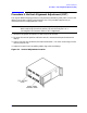
5. Connect an electrical delay of known length between measurement PORT 1 and
measurement PORT 2. The device should have a low loss and exhibit a precisely known
electrical delay, as do the air lines in the 3.5 mm and 7 mm verification kits.
6. Enter the electrical delay of the air line by pressing
RESPONSE MENU, [ELECTRICAL
DELAY]
. The phase transitions should disappear, leaving a phase trace with some slope.
Any residual slope indicates a need to adjust trim sweep.
7. Press
CAL, [MORE], [TRIM SWEEP]. Use the knob to adjust the phase for a flat phase
trace. When the best (flattest) phase trace is achieved, press
SAVE,
[INSTRUMENT STATE n]
to save this setting. Now proceed with the appropriate
measurement calibration.
NOTE In the 8350 plug-in firmware at 7 GHz Band Cross 201 MHz span only, phase
measurements after trim sweep correction can still result in a
≥ 75° step at
the band cross points due to switching of the RF to the wrong band.