Agilent Technologies 8510C Network Analyzer System Service Quick Reference Guide Manufacturing Part Number: 08510-90317 Printed in USA Print Date: February 2005 Revision 3.
Restricted Rights Legend Use, duplication, or disclosure by the U.S. Government is subject to restrictions as set forth in subparagraph (c)(1)(ii) of the Rights in Technical Data and Computer Software clause at DFARS 252.227-7013 for DOD agencies, and subparagraphs (c)(1) and (c)(2) of the Commercial Computer Software Restricted Rights clause at FAR 52.227-19 for other agencies.
Typeface Conventions Italics • Used to emphasize important information: Use this software only with the Agilent Technologies xxxxxX system. • Used for the title of a publication: Refer to the Agilent Technologies xxxxxX System-Level User's Guide. • Used to indicate a variable: Type LOAD BIN filename. Instrument Display • Used to show on-screen prompts and messages that you will see on the display of an instrument: The Agilent Technologies xxxxxX will display the message CAL1 SAVED.
Contacting Agilent This information supersedes all prior HP contact information. Online assistance: www.agilent.
Contents 1 Agilent 8510C Installation Preflight Checkout . . . . . . . . . . . . . . . . . . . . . . . . . . . . . . . . . . . . . . . . . . . . . . . . . . . . . . . . . . .1-3 2 Instrument Compatibility Upgrading an 8340/8350 Source . . . . . . . . . . . . . . . . . . . . . . . . . . . . . . . . . . . . . . . . . . . . . . . .2-2 Upgrading an 8360 Source. . . . . . . . . . . . . . . . . . . . . . . . . . . . . . . . . . . . . . . . . . . . . . . . . . . . .2-3 8360 Series Coupler to Bridge Detector .
Contents Contents-vi 8510C Service Quick Reference Guide
1 Agilent 8510C Installation 8510C Service Quick Reference Guide 1-1
Agilent 8510C Installation 1-2 8510C Service Quick Reference Guide
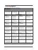
8510C Installation "Preflight Checkout" Security Keys for 85101C Security Board A8 85101-69268 < Opt. 010 85101-80091 08530-69001 < Antenna 08530-80004 CRT Only 85101-69273 < Rev. 6.XX – Rev. 8.XX 85101-80114 Rev. C.06.60 85101-80132 CRT Only Rev. C.07.XX 85101-80116 CRT Only Rev. C.08.XX 85101-80116 LCD Only PRINTER ADDRESS 1 PLOTTER ADDRESS 5 For a complete list of compatible printers/plotters see the 8510C Ordering Guide.
Agilent 8510C Installation Preflight Checkout 1-4 8510C Service Quick Reference Guide
2 Instrument Compatibility 8510C Service Quick Reference Guide 2-1
Instrument Compatibility Upgrading an 8340/8350 Source Upgrading an 8340/8350 Source 8340/41 and 8350 series sources are out of support life and are no longer recommended for use in 8510C systems. Not all 8340/41 sources are compatible with the 8510B/C. If the serial prefix is not 2505A or greater, or previously upgraded, the firmware may need to be upgraded to get full performance (within feature limitations) and a minimum of bugs. For example, with Nov.
Instrument Compatibility Upgrading an 8360 Source Upgrading an 8360 Source All 8360 series instruments are compatible, but not all allow use of quick-step, test-port power flatness correction, receiver calibration, and power domain functions without upgrading them. Refer to Table 2-1 for upgrades required for these functions. 8510C revision C.07.00 or greater firmware requires use of an 8360 series source for complete compatibility. Revision C.06.
Instrument Compatibility 8360 Series Coupler to Bridge Detector 8360 Series Coupler to Bridge Detector All 8510B/C systems when used with an 8360 series source that have a bridge detector inside will potentially cause an over-modulation running error message. If your 8510C has Rev.7.0 or greater, an RF unleveled caution message will also be displayed.
Instrument Compatibility Dedicated 8510 System Source Models Dedicated 8510 System Source Models Dedicated sources are optimized for use as 8510 system components. They are configured without modulation capabilities or front panel keyboard/displays. They have rear connectors, and one-year on-site service where available. Specifications for these models are the 8510 specifications with the following additions: Frequency Range (all serial prefixes) 83621A/B 45 MHz to 20 GHz 83631A/B 45 MHz to 26.
Instrument Compatibility Dedicated 8510 System Source Models Table 2-2 RF Output Power (Prefix ≥ 3145A) Maximum Leveled (dBm) Standard Option 006 8360A/B, 83622A/B1 +13 +13 83623A/B +17 +17 83624A/B +20 +20 Output frequencies < 20 GHz +13 +13 Output frequencies ≥ 20 GHz +10 +10 Output frequencies < 26.5 GHz +10 +10 Output frequencies ≥ 26.5 GHz +6 +6 Output frequencies < 26.5 GHz +10 +10 Output frequencies ≥ 26.5 GHz and < 40 GHz +5 +5 Output frequencies ≥ 40 GHz +2.5 +2.
Instrument Compatibility Dedicated 8510 System Source Models Figure 2-1 Typical Maximum Available Power With attenuator (Option 001): Maximum leveled output power is reduced by 1.5 dB to 20 GHz, 2 dB above 20 GHz, and 2.5 dB above 40 GHz. Minimum Settable Output Power Std: − 20 dBm Opt 001: − 110 dBm Resolution 0.02 dB Switching Time (without attenuator change) 10 ms, typical Temperature Stability 0.
Instrument Compatibility Compatible External Monitors Compatible External Monitors NOTE The original 85101C display/processor incorporated a cathode ray tube (CRT). The current design incorporates a liquid crystal display (LCD). Refer to the NOTE on page 2-9 for more information on determining the type of display. Monitors for Models with a CRT Display The 8510C with a CRT installed is designed to work with monitors that have these four specifications: • Horizontal scan rate of 25.
Instrument Compatibility Displays Displays NOTE The original 85101C display/processor (8510C top box) incorporated a cathode ray tube (CRT). An 85101C with a CRT display has a serial prefix of 3936A and lower or a serial prefix of US4116, and uses 8510C firmware revision C.07.xx. The current 85101C display/processor (8510C top box) incorporates a liquid crystal display (LCD). An 85101C with a LCD has a serial prefix of 4116A and higher, and uses 8510C firmware revision C.08.xx. Cleaning the CRT 1.
Instrument Compatibility Displays Figure 2-2 Removing the Glass Filter Cleaning the LCD Use a soft cloth and, if necessary, a cleaning solution recommended for optical coated surfaces. Agilent part number 8500-2163 is one such solution. Enhancement Annotation Area Along the left side of the screen, one-character labels appear when you select network analyzer functions that affect the accuracy or presentation of the measurement trace (see Figure 2-2).
3 8510C Adjustments 8510C Service Quick Reference Guide 3-1
8510C Adjustments Most of the 8510C is self adjusting. Table 3-1 lists the adjustments most frequently needed for 8510C system service.
8510C Adjustments Procedure 1. Vertical Alignment Adjustment (CRT) Procedure 1. Vertical Alignment Adjustment (CRT) The original 85101C display/processor incorporated a cathode ray tube (CRT). The current design incorporates a liquid crystal display (LCD). This procedure applies only to instruments that are equipped with a CRT. NOTE The vertical alignment can be adversely affected by magnetic interference.
8510C Adjustments Procedure 2. Degaussing (Demagnetizing) the CRT Display Procedure 2. Degaussing (Demagnetizing) the CRT Display NOTE This procedure applies only to instruments equipped with a CRT. The color monitor display is very susceptible to external magnetic fields, such as metal frame tables, welded cabinet, the earth, unshielded motors, and other sources. The usual symptom is discoloration or slight dimming of the display (usually near a top corner of the CRT).
8510C Adjustments Procedure 2. Degaussing (Demagnetizing) the CRT Display Like most displays, the CRT can be sensitive to large magnetic fields generated from unshielded motors. In countries using 50 Hz, some 10 Hz jitter may be observed. If this problem is observed, remove the device causing the magnetic field. Figure 3-2 shows the motion for degaussing the display.
8510C Adjustments Procedure 3. 8350B/Plug-ins Front Panel FREQ CAL Procedure 3. 8350B/Plug-ins Front Panel FREQ CAL 1. Press 8350B INSTR PRESET, CW, 50, MHz. 2. Connect the external frequency counter through a 10 dB attenuator to the RF OUTPUT. 3. Adjust the FREQ CAL control for a frequency counter indication of 50.0 MHz. Alternate Procedure This alternate FREQ CAL procedure is not as accurate as using an external counter, but normally calibrates the Band 0 frequency accuracy within specifications. 1.
8510C Adjustments Procedure 5. Trim Sweep Procedure 5. Trim Sweep Trim Sweep performs a different function for 8340/41 and 8350 sources. For 8340 sources set for ramp sweep mode, it is used to adjust the band-switch points to minimize the frequency difference between the end frequency of one band and the start frequency of the next higher band. Trim Sweep is not used in the step-sweep mode. For 8350 sources, trim sweep is adjusted to provide the best frequency accuracy.
8510C Adjustments Procedure 5. Trim Sweep be a flat line at 0 °. 5. Connect an electrical delay of known length between measurement PORT 1 and measurement PORT 2. The device should have a low loss and exhibit a precisely known electrical delay, as do the air lines in the 3.5 mm and 7 mm verification kits. 6. Enter the electrical delay of the air line by pressing RESPONSE MENU, [ELECTRICAL DELAY]. The phase transitions should disappear, leaving a phase trace with some slope.
4 Performance Verification 8510C Service Quick Reference Guide 4-1
Performance Verification This page intentionally left blank.
Performance Verification Preparation for Performance Verification Preparation for Performance Verification Table 4-1 lists the equipment needed to run the tests. Table 4-1 Equipment Requireda • 8510C network analyzer and accessories • test set • sourceb • For PC based Performance Verification — Laptop or PC running BASIC for Windows (Rev. 6.32 or greater under Windows 95/98/NT).
Performance Verification Preparation for Performance Verification Prepare for Performance Verification tests by completing the following steps: • Do a good installation “preflight” checkout on the 8510 system. • Measure the environment temperature and humidity. The temperature must be between +20 °C and +26 °C. Then the temperature cannot vary more than ± 1 °C after calibration. • Turn on the system components in the following order and allow one hour warm-up time. 1. Source 2. Test set 3. 8510C 4.
Performance Verification CW Frequency Accuracy Test CW Frequency Accuracy Test Source frequency accuracy is tested across the entire sweep range for 8340/8360 sources only. Measure CW frequency accuracy with a frequency counter. The 8350 source frequency accuracy is tested during the total system uncertainty test. Front panel emulation software (included in the 8510 operating system disk) is required to test an 83621/31/51.
Performance Verification CW Frequency Accuracy Test Be sure to connect the test set output to the 500 MHz − 26.5 GHz position input on the frequency counter. Also set the input switch to the 500 MHz − 26.5 GHz position. NOTE 6. Measure the frequency with the counter, and record the value on the test record as in Table 4-2.
Performance Verification Automated Performance Tests Automated Performance Tests This test requires the following disks: • BASIC 5.0 or greater • Language extension disks (Clock, MAT, Graph, and I/O) • Drivers disk (GPIB) • Performance Verifications Software, Revision A.05.01 (part number 08510-10033) Loading the Language Disks and Software 1. Load BASIC 5.0 or higher into the disk drive for autostart on your controller. Press SHIFT, PAUSE or cycle the power of the controller to activate autostart.
Performance Verification Automated Performance Tests 5. Insert the performance verification disk (08510-10033) into the right-hand drive 0. Type: “LOAD SPECS_8510”, then press EXECUTE. NOTE There is no need to connect the 8510 to generate system specification; therefore, ignore display prompts about connecting the 8510. NOTE Remember for sliding load cal that lowband or broadband loads can be used for lowband. Do not perform broadband cal if doing sliding load cal.
Performance Verification Optional Swept Frequency Accuracy Check Optional Swept Frequency Accuracy Check For Swept-Frequency/Ramp Mode Only This procedure is helpful for systems that are primarily operated in ramp mode. Typically step mode is used. If only step mode is used, you may skip this check. This procedure is not part of Performance Verification. Performance Verification requires step mode. This procedure is not for 8350 series sources.
Performance Verification Optional Swept Frequency Accuracy Check Procedure For 8360 Synthesizers From the front panel or the emulator program (see kit for instructions): 1. To initiate an auto track, press the following synthesizer keys: PRESET, USER CAL, [Tracking Menu], [Auto Track], [Proceed] 2. To initiate a sweep span calibration, press the following synthesizer keys: PRESET, USER CAL, FREQ CAL MENU, [ONCE] (No visual response is displayed after pressing the [ONCE] key.
Performance Verification Optional Swept Frequency Accuracy Check Figure 4-3 Full Span Response at 1 MHz per Division For 8340/41 Series Synthesizers Position the highest frequency bandswitch transition point on to the reference line. Press synthesizer keys: CAL, [MORE], [TRIM SWEEP] and then adjust the front panel knob. Record the maximum trace variation on the test record. Figure 4-4 shows a typical display.
Performance Verification Optional Swept Frequency Accuracy Check Table 4-4 Performance Test Record for Optional Test Instrument Model Report Number Date ______________ ____________ ___________ Test Description Recorded Results Maximum Specification Measurement Uncertaintya _____________ 0.1% of sweep (for 8360) ± 150 kHz _____________ 1% of sweep ± 150 kHz Swept Frequency Accuracy Start Frequency: ________________ Stop Frequency: ________________ a.
A Troubleshooting Flowchart and Block Diagrams 8510C Service Quick Reference Guide A-1
Troubleshooting Flowchart and Block Diagrams A-2 8510C Service Quick Reference Guide
Troubleshooting Flowchart and Block Diagrams System Flow Chart (1 of 2) Figure A-1 System Flow Chart (1 of 2) 8510C Service Quick Reference Guide A-3
Troubleshooting Flowchart and Block Diagrams System Flow Chart (2 of 2) Figure A-2 System Flow Chart (2 of 2) A-4 8510C Service Quick Reference Guide
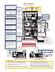
Troubleshooting Flowchart and Block Diagrams System Level Troubleshooting Block Diagram (CRT) A-10 8510C Service Quick Reference Guide
Troubleshooting Flowchart and Block Diagrams System Level Troubleshooting Block Diagram (LCD) A-12 8510C Service Quick Reference Guide