Agilent 16800 Series Portable Logic Analyzers Service Guide Agilent Technologies
Notices © Agilent Technologies, Inc. 2006, 2007 Manual Part Number No part of this manual may be reproduced in any form or by any means (including electronic storage and retrieval or translation into a foreign language) without prior agreement and written consent from Agilent Technologies, Inc. as governed by United States and international copyright laws. 16800-97004 Trademark Acknowledgements Windows and MS Windows are U.S. registered trademarks of Microsoft Corporation. Windows XP is a U.S.
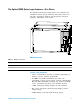
The Agilent 16800 Series Logic Analyzers—At a Glance The Agilent Technologies 16800 Series logic analyzers are standalone benchtop logic analyzers that range from 34 to 204 logic acquisition channels and 48 pattern generator channels, depending on the model.
Features, Mainframe • Built- in 15 inch TFT color LCD display, 1,024 x 768 (XGA) resolution. Touch screen with 16800A Option 103. • 80 GB hard disk drive (or external hard drive 16800A Option 109). • 10/100 Base- T LAN port. • USB 2.0 ports (six total, two on front, four on back). • One PCI expansion slot. • One PCI Express x1 expansion slot. • Windows® XP Professional operating system. • Agilent Logic Analyzer application which takes the complexity out of making logic analyzer measurements.
This instrument can be returned to Agilent Technologies for all service work, including troubleshooting. Contact your nearest Agilent Technologies Sales Office for more details. Contacting Agilent Technologies To locate a sales or service office near you, go to www.agilent.com/find/contactus.
In this Service Guide This book is the service guide for the 16800 Series logic analyzers and is divided into eight chapters. Chapter 1, “General Information” contains information about the instrument including accessories, specifications and characteristics, and a list of the equipment required for servicing the instrument. Chapter 2, “Preparing for Use” tells how to prepare the instrument for use. Chapter 3, “Testing Performance” gives instructions on how to test the performance of the instrument.
Contents 1 General Information Accessories Available Specifications 14 14 15 Characteristics 16 Electrical 16 Operating Environment (for indoor use only) Non-Operating Environment 17 Dimensions 18 Weight 18 Recommended Test Equipment 2 19 Preparing for Use To inspect the logic analyzer To apply power 22 22 To clean the instrument 23 To start the user interface To test the logic analyzer 3 17 23 23 Testing Performance To perform the power-up tests 26 Logic Analyzer Test Strategy 27 Test Inte
Contents Prepare the Logic Analyzer for Testing Perform System Self-Tests 36 Set Up the Test Equipment 35 37 Connect the Test Equipment 39 Connect the Logic Analyzer Pod to the 8133A Pulse Generator Connect the 8133A Pulse Generator Output to the 54845A Oscilloscope 40 Verify and adjust 8133A pulse generator DC offset 41 Deskew the oscilloscope 42 Set the 8133A pulse width 43 Configure the Logic Analyzer 45 Adjust the sample positions using eye finder 39 48 Test Pod 1 in 250 Mb/s Mode 52 Determine PA
Contents 5 Troubleshooting To use the system troubleshooting flowcharts 72 To use the logic acquisition troubleshooting flowcharts 78 To use the pattern generator troubleshooting flowcharts To troubeshoot system power problems Power Supplies 84 To check the power supply voltages 84 84 To run the self-tests 88 Logic Acquisition Self-Test Descriptions Pattern Generator Self-Tests Description To exit the test system 96 To reinstall the operating system 81 89 92 97 To test the logic acquisition cabl
Contents To remove and replace the front panel bracket assembly To remove and replace the USB cables 128 129 To remove and replace the display assembly 130 To remove and replace the keypad and keypad board 132 To remove and replace a measurement card 134 To remove and replace measurement cables 135 To remove and replace a measurement circuit board 137 To remove and replace a pattern generator card 138 To remove and replace the pattern generator probe cable 139 To remove and replace the pattern gen
Contents Logic Acquisition Block-Level Theory 180 Probes 181 Comparators 181 Acquisition IC 181 Memory Controller and Acquisition Memory 182 Master/Expander Connectors 182 Mainframe Interface and Control FPGA 182 Pattern Generation Block-Level Theory Instruction Memory 183 Data Memory 183 Output Driver 184 Clock Circuit 184 CPU Interface 184 Pod 185 183 Index 16800 Series Portable Logic Analyzers Service Guide 11
Contents 12 16800 Series Portable Logic Analyzers Service Guide
Agilent 16800 Series Portable Logic Analyzers Service Guide 1 General Information Accessories 14 Specifications 15 Characteristics 16 Recommended Test Equipment 19 This chapter contains information on accessories, specifications, characteristics, and recommended test equipment. See the 16800 Series logic analyzer’s online help for a full listing of all specifications and characteristics.
1 General Information Accessories Available One or more of the following accessories, sold separately, are required to operate the 16800 Series logic analyzers.
1 General Information Specifications The specifications are the performance standards against which the product is tested. tWidth (Data Eye) Individual Data Channel vHeight Sampling Position (Eye Finder Blue Bar) vThreshold 0V Specifications Parameter 250 Mb/s mode 500 Mb/s mode Notes Minimum master to master clock time 4 ns 2 ns 500 Mb/s mode is available only when Option 500 is installed. tWidth (minimum) 1.5 ns 1.5 ns Specified at probe tip.
1 General Information Characteristics The following characteristics are not specifications, but are typical characteristics for the 16800 Series logic analyzers. Electrical Power Requirements 16801A, 16802A, and 16803A: 115/230 Vac +/- 20%, 48- 66Hz, 615 W Max. 16804A, 16806A, 16821A, 16822A, and 16823A: 115/230 Vac +/- 20%, 48- 66Hz, 775 W Max. The line voltage is autodetected by the instrument. CAT II (Line voltage in appliance and to wall outlet). Pollution degree 2.
General Information 1 Operating Environment (for indoor use only) Table 4 Operating Environment Characteristics Temperature All models: 0° to + 50° C (+32° to +122° F). Probes/cables: 0° to + 65° C (+32° to +149° F). Humidity Relative humidity 8% to 80% at 40° C (104° F). Avoid sudden, extreme temperature changes which could cause condensation on the circuit board. Altitude 0 to 3,000 m (10,000 ft) Vibration Operating: random vibration 0-500 Hz, 10 minutes per axis, 0.3 g (rms).
1 General Information Dimensions The following figure provides dimensions for the 16800 Series logic analyzer mainframes in centimeters and inches. Weight Table 6 18 16800 Series Logic Analyzer Weight Model Max Net Max Shipping 16801A 12.9 kg (28.5 lbs) 19.7 kg (43.5 lbs) 16802A 13.2 kg (28.9 lbs) 19.9 kg (43.9 lbs) 16803A 13.7 kg (30.3 lbs) 20.5 kg (45.3 lbs) 16804A 14.2 kg (31.3 lbs) 21.0 kg (46.3 lbs) 16806A 14.6 kg (32.1 lbs) 21.4 kg (47.1 lbs) 16821A 14.2 kg (31.2 lbs) 20.
General Information 1 Recommended Test Equipment Table 7 Recommended Test Equipment Equipment Critical Specifications Recommended Agilent Model/Part Use† Single-ended Flying Lead Probe Set (Qty 2) no substitute E5383A P, T Ground Leads (Qty 5) no substitute pkg of 5 (Included with E5383A Probe Set) T Pulse Generator 260 MHz,1 ns pulse width, two channels, ≤ 150 ps rise time 8133A Option 003 P, T 150 ps Transition Time Converter (Qty 4) Required if pulse generator’s rise time is less tha
1 20 General Information 16800 Series Portable Logic Analyzers Service Guide
Agilent 16800 Series Portable Logic Analyzers Service Guide 2 Preparing for Use To inspect the logic analyzer 22 To apply power 22 To clean the instrument 23 To start the user interface 23 To test the logic analyzer 23 Agilent Technologies 21
2 Preparing for Use To inspect the logic analyzer 1 Inspect the shipping container for damage. If the shipping container or cushioning material is damaged, keep them until you have checked the contents of the shipment and checked the instrument mechanically and electrically. WA R N I N G Hazardous voltages exist in this instrument. To avoid electrical shock, do not apply power to a damaged instrument. 2 Check the supplied accessories. Accessories supplied with the logic analyzer are listed on page 4.
Preparing for Use 2 • Look under Technical Support and then Manuals and Guides. To clean the instrument If the instrument requires cleaning: 1 Remove power from the instrument. 2 Clean the external surfaces of the instrument with a soft cloth dampened with a mixture of mild detergent and water. 3 Make sure that the instrument is completely dry before reconnecting it to a power source. To start the user interface Start the Agilent Logic Analyzer application from the Start menu or using a shortcut.
2 24 Preparing for Use 16800 Series Portable Logic Analyzers Service Guide
Agilent 16800 Series Portable Logic Analyzers Service Guide 3 Testing Performance To perform the power-up tests 26 Logic Analyzer Test Strategy 27 To Assemble the SMA/Flying Lead Test Connectors 28 To Test the Minimum Master to Master Clock Time and Minimum Eye Width 33 Equipment Required 34 Prepare the Logic Analyzer for Testing 35 Set Up the Test Equipment 37 Connect the Test Equipment 39 Configure the Logic Analyzer 45 Test Pod 1 in 250 Mb/s Mode 52 Test Pod 2 in 250 Mb/s Mode 57 Test Pods 3 and 4 in 25
3 Testing Performance Directions for performing power- up tests and the logic acquisition card’s manual performance verification tests (against the specifications listed on page 15) are given in this chapter. The logic analyzer is considered performance- verified if the power- up tests, the self- tests, and the manual performance tests have passed. The procedures in this chapter indicate what constitutes a “Pass” status for each of the tests.
3 Testing Performance Logic Analyzer Test Strategy Only specified parameters are tested. Specifications are listed on page 15. The test conditions defined in this procedure ensure that the specified parameter is as good as or better than specification. No attempt is made to determine performance which is better than specification. Not all channels of the logic analyzer will be tested; rather a sample of channels is tested.
3 Testing Performance To Assemble the SMA/Flying Lead Test Connectors The SMA/Flying Lead test connectors provide a high- bandwidth connection between the logic analyzer and the test equipment. The following procedure explains how to fabricate the required test connectors. Table 8 Materials Required for SMA/Flying Lead Test Connectors Material Critical Specification SMA Board Mount Connector (Qty 6) Recommended Model/Part Johnson 142-0701-801 (see www.johnsoncomponents.
Testing Performance 3 1 Prepare the pin strip header: a Cut or cleanly break a 2 x 2 section from the pin strip. b Trim about 1.5 mm from the pin strip inner leads and straighten them so that they touch the outer leads. c Trim about 2.5 mm from the outer leads. solder d Using a very small amount of solder, tack each inner lead to each outer lead at the point where they are touching.
3 Testing Performance 2 Solder the pin strip to the SMA board mount connector: a Solder the leads on the left side of the pin strip to the center conductor of the SMA connector as shown in the diagram below. b Solder the leads on the right side of the pin strip to the inside of the SMA connector’s frame as shown in the diagram below. Use a small amount of solder.
Testing Performance 3 strip, and the center conductors of each SMA connector. b Ensure that there is continuity between each of the two pins on the right side of the pin strip, and the SMA connector frames. c Ensure that there is NO continuity between the SMA connector center conductor and the SMA connector frame (ground).
3 Testing Performance 5 Finish creating the test connectors: a Attach an SMA m- m adapter to one end of each of the three SMA/Flying Lead test connectors. b Attach a 50 ohm terminator to the other end of just one of the SMA/Flying Lead test connectors. c The finished test connector is shown in the pictures below.
Testing Performance 3 To Test the Minimum Master to Master Clock Time and Minimum Eye Width The specifications for the logic analyzer define a minimum master to master clock time and a minimum data eye width at which data can be acquired. This test verifies that the logic analyzer meets these specifications. Eye finder is used to adjust the sampling position on every tested channel. Eye finder must be used to achieve minimum data eye width performance.
3 Testing Performance Equipment Required The following equipment is required for the performance test procedure. Table 9 Equipment Required Equipment Critical Specification Recommended Model/Part Pulse Generator ≥ 260 MHz, two channels, differential outputs, 150-180 ps rise/fall time (if faster, use transition time converters) Agilent or HP 8133A option 003 150 ps Transition Time Converter (Qty 3) Required if pulse generator’s rise time is less than 150 ps.
3 Testing Performance Prepare the Logic Analyzer for Testing 1 Record the logic analyzer’s model and serial number in the Performance Test Record (see page 68). Record your work order number (if applicable) and today’s date. 2 Record the test equipment information in the “Test Equipment Used” section of the Performance Test Record. 3 Turn on the logic analyzer. a Connect the keyboard to the rear panel of the logic analysis mainframe. b Connect the mouse to the rear panel of the mainframe.
3 Testing Performance Perform System Self-Tests Perform a self- test on the logic analyzer: 1 When the logic analyzer has finished booting, the Waveform window appears. Select Help→Self-Test... from the main menu. The Analysis System Self Tests dialog appears. 2 In the Select Suite(s) list, select . This will cause to be selected in the Select Test(s) list. 3 Select Start. This will perform a complete system self- test.
Testing Performance 3 Set Up the Test Equipment 1 Turn on the required test equipment. Let all of the test equipment and the logic analyzer warm up for 30 minutes before beginning any test. 2 Set up the pulse generator according to the following table. a Set the frequency of the pulse generator. In this test procedure, the logic analyzer uses both edges of the clock to acquire data.
3 Testing Performance Table 11 Oscilloscope Setup Setup: Channel 1 Setup: Ch. 1 Probe Setup: Channel 2 Setup: Ch. 2 Probe On Attenuation: 1.00:1 On Attenuation: 1.00:1 Scale: 100 mV/div Units: Volts Scale: 100 mV/div Units: Volts Offset: 1 V Attenuation Units: Ratio Offset: 1 V Attenuation Units: Ratio Coupling: DC External Gain: (n/a) Coupling: DC External Gain: (n/a) Input: 50 ohm Skew: (Set later. See page 42) Input: 50 ohm Skew: 0.
Testing Performance 3 Connect the Test Equipment Connect the Logic Analyzer Pod to the 8133A Pulse Generator 1 Connect a Transition Time Converter (if required—see Table 7, “Recommended Test Equipment,” on page 19) to the 8133A pulse generator’s Channel 2 OUTPUT, Channel 2 OUTPUT, and Channel 1 OUTPUT.
3 Testing Performance NOTE For each Flying Lead Probe connection, be sure to use a black ground lead (five are supplied with the E5383A Flying Lead Probe Set) and orient the leads so that the ground leads are connected to the SMA/Flying Lead connector’s ground pins! If you don’t have the ground leads, you can push the probe body’s ground socket directly onto a ground pin on the SMA/Flying Lead test connector.
Testing Performance 3 Verify and adjust 8133A pulse generator DC offset 1 On the 54845A oscilloscope, select Measure from the menu bar at the top of the display. 2 Select Markers... 3 In the Markers Setup dialog set marker “Ay” to 0.7 V, and set marker “By” to 1.3 V. 4 Observe the waveforms on the oscilloscope display. If they are not centered within the “Ay” and “By” markers, adjust the 8133A pulse generator’s Channel 2 OFFSET until the waveforms are centered as close as possible.
3 Testing Performance Deskew the oscilloscope This procedure neutralizes any skew in the oscilloscope’s waveform display. 1 On the 54845A oscilloscope, change the Horizontal scale to 200 ps/div. You can do this using the large knob in the Horizontal setup section of the front panel. 2 Select Setup from the menu bar at the top of the display. 3 Select Channel 1. 4 Select Probes.
Testing Performance 3 6 Select Close in the Probe Setup dialog. 7 Select Close in the Channel Setup dialog. Set the 8133A pulse width 1 On the 8133A pulse generator, set the Channel 2 pulse width to 1.5 ns. 2 Observe the 54845A oscilloscope display. Change the Channel 2 pulse width of the 8133A pulse generator so that the pulse width measured at 1 volt on the oscilloscope is equal to 1.
3 Testing Performance NOTE 44 On the oscilloscope move the Ax and Bx markers to the crossing points of the pulse and the horizontal center line. Read the pulse width at the bottom of the screen. It is displayed as “∆=”.
3 Testing Performance Configure the Logic Analyzer 1 Exit the Agilent Logic Analyzer application (from the main menu, choose File→Exit) and then restart the application. This puts the logic analyzer into its initial state. 2 Specify the threshold voltage and assign channels to the bus name: a From the main menu, select Setup→Bus/Signal... or Setup→My Logic Analyzer-1→Bus/Signal.... b In the Analyzer Setup dialog, choose the Threshold button for Pod 1.
3 Testing Performance c In the Threshold Settings dialog, set the threshold value for Pod 1 of the logic analyzer to 1 V, and click OK. d The activity indicators now show activity on the channels that are connected to the pulse generator. e Un- assign all channels. Hint: you can do this quickly by clicking on the left- most check mark and dragging to the right across all of the other check marks.
Testing Performance 3 3 Set the sampling mode. a Select the Sampling tab of the Analyzer Setup dialog. b Select State - Synchronous Sampling. c Set the Trigger Position to 100% Poststore. d Set the Acquisition Depth to 128K. e Clear the Timing Zoom check box to turn Timing Zoom off. f Ensure that the sampling speed is set to 250 MHz in the Sampling Options box.
3 Testing Performance NOTE If option 500 is not installed on the logic analyzer, then 250 MHz will be the only speed available. g Ensure that the Clock Mode is set to Master. h Set the Pod 1 master clock to Both Edges. Adjust the sample positions using eye finder 1 Click Thresholds and Sample Positions.... 2 In the “Buses/Signals” section of the Thresholds and Sample Positions dialog, ensure that the check box next to “My Bus 1” is checked.
3 Testing Performance 3 Select the plus sign to expand bus “My Bus 1”. Align the blue bars vertically The first time you run eye finder, the blue bars will already be vertically aligned (as shown above). In this case you can skip to the next section (“Run eye finder”). After running eye finder, the blue bars will not be vertically aligned because an independent sample position will be determined for each channel.
3 Testing Performance The important point is that your eye finder display should look similar to the picture below (although it may be shifted left or right), and eye finder must be able to place the blue bars in the narrow eye. (The example below shows eye finder in the 250 Mb/s mode.) To re-align a stray channel If the blue bar for a particular bit does not appear in its eye near the recommended starting position, then do the following steps to realign the sampling position of the stray channel.
Testing Performance 3 The following example shows all sampling positions aligned and in the correct eye.
3 Testing Performance Test Pod 1 in 250 Mb/s Mode The steps that follow include pass/fail criteria. Determine PASS/FAIL (1 of 2 tests) 1 PASS/FAIL: If an eye exists near 300 ps for every bit, and eye finder places a blue bar in the narrow eye for each bit, then the logic analyzer passes this portion of the test. Record the result in the “Test 1 of 2: eye finder locates an eye for each bit” section of the Performance Test Record (page 68).
Testing Performance 3 3 Data appears in the Listing window upon completion of the run. 4 From the main menu choose Markers→New.... a You can accept the default name for the new marker. b Change the Position field to Value. c Click Occurs..., and create the marker setup shown below. Click here to add event Click here to select “Or” 5 In the Value dialog, click Properties.... 6 In the Value Properties dialog, select Stop repetitive run when value is not found.
3 Testing Performance Determine PASS/FAIL (2 of 2 tests) Pass/Fail Point: The Listing window is set up to search for the appropriate number of A's and 5's in the acquisition. If the logic analyzer does not detect the correct number of A’s and 5’s, an error dialog will appear. 1 Click the Run Repetitive icon . Let the logic analyzer run for about one minute. The analyzer will acquire data and the Listing window will continuously update.
Testing Performance NOTE 3 As a point of curiosity, you may want to determine the absolute minimum pulse width and/or absolute maximum frequency at which data can be acquired. The “Performance Test Record" on page 68 does not include places for recording these values because the Performance Verification procedure only verifies that the logic analyzer meets specifications. Determination of additional parameters is not required, but may be performed at the discretion of the calibration laboratory.
3 Testing Performance 6 Adjust the sampling positions using eye finder. See page 48. 7 Determine pass or fail (1 of 2 tests). See page 52. 8 Switch to the Listing window by selecting the Listing tab at the bottom of the main logic analyzer window. 9 Click the Run Repetitive icon . 10 Determine pass or fail (2 of 2 tests). See page 54.
Testing Performance 3 Test Pod 2 in 250 Mb/s Mode 1 Disconnect the E5383A Flying Lead Probe Set from Pod 1 and connect it to Pod 2 of the logic analyzer. Do not remove the flying leads that are connected to CLK and the data channels. 2 On the 8133A pulse generator, in the PULSE setup for CHANNEL 2, press the COMP button to return the outputs to normal. 3 Note that the signal on the oscilloscope has moved.
3 Testing Performance 13 Adjust the sampling positions using eye finder. Be sure to expand “My Bus 1” and use the recommended starting position noted on page 49. Realign any stray channels if necessary. See page 50. 14 Determine pass or fail (1 of 2 tests). See page 52. 15 Click OK to close the “Analyzer Setup” dialog. 16 Switch to the Listing window by selecting the Listing tab at the bottom of the main logic analyzer window. 17 Click the Run Repetitive icon .
3 Testing Performance Test the Remaining Pods in 250 Mb/s Mode The logic analyzer master card’s Pod 1 clock (“Clk1” in the Sampling setup dialog) is used for testing all Pods above 4 in the 250 Mb/s mode. Therefore, two E5383A Flying Lead Probe Sets are required to test the remaining pods. Set up the second E5383A Flying Lead Probe Set 1 Disconnect the first E5383A Flying Lead Probe Set from the pod it is currently connected to (Pod 4) and connect it to the pod under test (Pod 5).
3 Testing Performance Test Pod 1 in 500 Mb/s Mode NOTE If option 500 is not installed on the logic analyzer, then 250 MHz will be the only speed available. In this case, write “n/a” in the 500 Mb/s mode boxes in the Performance Test Record and proceed to “Conclude the State Mode Tests” on page 66. Clock “Clk1” will be used for testing all pods in the 500 Mb/s mode. Therefore two E5383A Flying Lead Probe sets will be required when testing the remaining pods.
Testing Performance 3 Determine and set eye finder Position (500 Mb/s mode) 1 On the 8133A pulse generator, in the PULSE setup for CHANNEL 2, press the COMP button to return the outputs to normal. 2 Change the oscilloscope’s horizontal position to 725 ps (or as required) to center the measured pulse on the oscilloscope display. 3 Verify the DC offset and adjust it if necessary. See page 41. 4 Verify the oscilloscope Deskew and adjust if necessary. See page 42.
3 Testing Performance may be different based on your test setup. Bring stray channels into alignment if necessary. See page 50. 12 Now set the pulse generator to the new test frequency. The logic analyzer will be tested using a double- edge clock. The test frequency is half the test clock rate because data is acquired on both the rising edge and the falling edge of the clock. Set the frequency to 250 MHz plus the frequency uncertainty of the pulse generator, plus a test margin of 1%.
3 Testing Performance 18 Run eye finder again. Some eyes may close, but the eyes in the sampling position you chose on page 61 should remain open. When you close the Analyzer Setup dialog a dialog may appear. If so, answer Yes to erase the data and continue. 19 Perform the procedure “Determine PASS/FAIL (1 of 2 tests)” on page 52. 20 Click the Run Repetitive icon . 21 Perform the procedure “Determine PASS/FAIL (2 of 2 tests)” on page 54.
3 Testing Performance Test Pod 2 in 500 Mb/s Mode The logic analyzer master card’s Pod 1 clock (“Clk1” in the Sampling setup dialog) is used for testing all Pods above 1 in the 500 Mb/s mode. Therefore, two E5383A Flying Lead Probe Sets are required to test Pod 2 and the remaining pods. Set up the second E5383A Flying Lead Probe Set 1 Disconnect the first E5383A Flying Lead Probe Set from the pod it is currently connected to (Pod 1) and connect it to the pod under test (Pod 2).
3 Testing Performance 9 Adjust the sampling positions using eye finder. Be sure to expand “My Bus 1”, align the blue bars vertically, and use the starting position you noted on page 61. Realign any stray channels if necessary. See page 50. 10 Determine pass or fail (1 of 2 tests). See page 52. 11 Switch to the Listing window. 12 Click the Run Repetitive icon . 13 Determine pass or fail (2 of 2 tests). See page 54.
3 Testing Performance To re-assign pods reserved for time tag storage 1 From the main menu, select Setup→Pod Assignment... or Setup→My Logic Analyzer-1→Pod Assignment... 2 In the Pod Assignment dialog, select pod pair A1/A2 to be reserved for time tag storage. 3 Click OK. 4 Reconfigure the markers to search for 131071 occurrences instead of 131072 (see “Configure the markers" on page 52). After re- assigning pod pairs, you can test pods that were previously reserved for time tag storage.
Testing Performance 3 the query “Do you want to save the current configuration?” select No. Ending and restarting the logic analysis session will re- initialize the system. b Disconnect all cables and adapters from the pulse generator and the oscilloscope.
3 Testing Performance Performance Test Record LOGIC ANALYZER MODEL NO. (circle one): 16801A, 16802A, 16803A, 16804A, 16806A, 16821A, 16822A, 16823A Logic Analyzer Serial No. Work Order No. Date: Recommended Test Interval - 2 Years Recommended next testing: TEST EQUIPMENT USED Pulse Generator Model No. Oscilloscope Model No. Pulse Generator Serial No. Oscilloscope Serial No.
Agilent 16800 Series Portable Logic Analyzers Service Guide 4 Calibrating and Adjusting Calibration Strategy 70 Agilent Technologies 69
4 Calibrating and Adjusting Calibration Strategy The 16800 Series logic analyzers do not require operational accuracy calibration.
Agilent 16800 Series Portable Logic Analyzers Service Guide 5 Troubleshooting To use the system troubleshooting flowcharts 72 To use the logic acquisition troubleshooting flowcharts 78 To use the pattern generator troubleshooting flowcharts 81 To troubeshoot system power problems 84 To check the power supply voltages 84 To run the self-tests 88 To reinstall the operating system 97 To test the logic acquisition cables 98 To verify pattern generator output 110 This chapter helps qualified service personnel
5 Troubleshooting To use the system troubleshooting flowcharts Flowcharts are the primary tool used to isolate defective assemblies. The flowcharts refer to other tests to help isolate the trouble. The circled references on the charts indicate connections with the other flowcharts or other parts within the same flowchart. A circled alpha references connections within the flowchart. Start your troubleshooting at the top of the first flowchart (Figure 1 on page 73).
Troubleshooting 1 5 Start Attach keyboard, mouse and power cord. Remove all user-installed PCI cards (see 'To remove & replace optional interface cards' in chapter 7. Apply power. Are the fans turning & power on? No 2 Yes Is the display screen readable? No 3 Yes Does the instrument finish booting to windows login? No 4 Yes Does the logic analyzer application start? No 5 Yes Run the module self tests. Do the self tests pass? No Go to module troubleshooting.
5 Troubleshooting 2 Remove power plug for 15 seconds to reset power supplies. Apply power. Are the fans turning & power on? Yes No Is the instrument at room temperature? No Yes Did fans come on for a second? 1 Let it cool and check for fan failure. Possible overtemp shutdown. The power down signal is asserted from CPU or MIB (module interface board). No Yes Try A , then B , then C . Return to 2 between each. The voltage monitor on the module interface board caused the shutdown.
Troubleshooting 5 3 Is there any boot dialog at any time? No Try Yes Proceed to boot up troubleshooting. A , then B . Return to 1 between each. A Check all cables to the front panel assembly. Check all cables to the CPU motherboard. Ensure the front panel board is fully seated. Reseat as necessary. B Connect a known good external monitor. NOTE: press and hold "Touch off" to switch between the internal and external monitors.
5 Troubleshooting 4 TYPICAL BOOT SEQUENCE DISPLAY ---------------------------------------------------1. Boot text 2. Agilent Technologies text and logo 3. Intel boot agent text 4. Select operating system menu 5. Windows XP boot screen (blue) 6. Checking file system text 7. Welcome to Windows login screen Does No the instrument reach #3 in the boot sequence? Yes Does the instrument reach #5 inthe boot sequence and is the power LED steady on? Failed BIOS boot. A Enter BIOS setup and reset to default.
5 Troubleshooting 5 Try each of the following steps in order. Return to 1 between each. A Reinstall the logic analyzer application. B Check all cables to front panel assembly . Check all cables to CPU motherboard. Check all cables to MIB board. Reseat as necessary. C Replace the MIB board. D Replace the PCI bridge board.
5 Troubleshooting To use the logic acquisition troubleshooting flowcharts Flowcharts are the primary tool used to isolate defective assemblies. The flowcharts refer to other tests to help isolate the trouble. The circled numbers on the charts indicate connections with the other flowchart. Start your troubleshooting at the top of the first flowchart. If the module still doesn't work correctly after completing all the procedures described in the flowchart, return it to Agilent Technologies for repair.
Troubleshooting Figure 6 5 Logic Acquisition Troubleshooting Flowchart 1 16800 Series Portable Logic Analyzers Service Guide 79
5 Troubleshooting Figure 7 80 Logic Acquisition Troubleshooting Flowchart 2 16800 Series Portable Logic Analyzers Service Guide
Troubleshooting 5 To use the pattern generator troubleshooting flowcharts Flowcharts are the primary tool used to isolate defective assemblies. The flowcharts refer to other tests to help isolate the trouble. The circled numbers on the charts indicate connections with the other flowcharts. Start your troubleshooting at the top of the first flowchart.
5 Troubleshooting Start 1 Apply Power Does the display show the module config correctly? No Is the current software version installed? Yes Install latest operating system version. No 1A Yes Are ALL cards properly seated in the mainframe? 2x10 cable faulty or not installed correctly between J3 and J6 on circuit board(s). Check 2x10 cable(s) Refer to Chapter 2. Yes No Do the procedure To run the self tests in Chapter 3 on the suspect module.
Troubleshooting 5 2 Is the user problem still present? Yes Perform procedure "To verify the pattern output" on suspect pod. No Does pattern output test pass? End Yes The module is functioning properly. Done No Replace pod with known good pod and repeat procedure. Does pattern output test pass? Yes Replace suspect pod. No Replace cable with known good cable and repeat procedure. Does the pattern output test pass? Yes Replace suspect cable. No Replace defective board.
5 Troubleshooting To troubeshoot system power problems If the system warns you it is powering down before it powers down, it is a fan/overtemp problem. If it just powers down, it is a power supply problem. If the lights do not come on and if the system powers up momentarily when you plug it in, make sure the power button hasn't become jammed or stuck in the pushed- in position.
5 Troubleshooting 5 Using a digital voltmeter, measure the DC power supply voltages. Use the following graphics when measuring the voltages. 6 Using a voltmeter, ensure the AUX +5V power on the MIB measures +5V. If it does not, replace the power supply. 7 Referring to the graphics that follow, note problems with the power supply, then return to Figure 2, “System Power Troubleshooting Flowchart,” on page 74. Use the following graphics when measuring the voltages.
5 Troubleshooting Power Supply Test Points on the 1-Slot, Low-Power Frame -12 +12 GND -5.2 -3.25 +3.3 +5 Power Supply Block Diagram of the 1-Slot, Low-Power Frame +3.3V 40A DC-DC Converter U57 (on MIB) +3.3V 25.6A MAX +5V 40A DC-DC Converter U58 (on MIB) +5V 11A MAX -5.2V 25A DC-DC Converter U59 (on MIB) -5.2V 11.2A MAX -12V 4A DC-DC Converter U55 (on MIB) -12V 0.6A MAX -3.25V 4A DC-DC Converter U56 (on MIB) -3.25V 3A MAX +3.3V +5V +5V AUX +3.
Troubleshooting 5 Power Supply Test Points on the 2-Slot, High-Power Frame -3.25 (slot B) -3.25 (slot A) -5.2 +3.3 -12 +12 +5 GND Power Supply Block Diagram of the 2-Slot, High-Power Frame +3.3V 40A DC-DC Converter U57 (on MIB) +3.3V 25.6A MAX +5V 40A DC-DC Converter U58 (on MIB) +5V 11A MAX -5.2V 25A DC-DC Converter U59 (on MIB) -5.2V 11.2A MAX +3.3V +5V +5V AUX +3.3V 12V 600W Power Supply +5V +12V -12V -5.2V -3.25V -3.25V 4A DC-DC Converter U55 (on MIB) -3.
5 Troubleshooting To run the self-tests The self- tests check the functional operation of the logic analyzer. Perform the self- tests as an acceptance test when receiving the logic analyzer or when the logic analyzer is repaired. 1 In the Agilent Logic Analyzer application, click Help>Self Test... 2 In the Analysis System Self Test dialog, double click on the test you want to run.
Troubleshooting 5 Logic Acquisition Self-Test Descriptions The self- tests for the logic analyzer identify the correct operation of major functional areas in the module. Interface FPGA Register Test The purpose of this test is to verify that the backplane interface can communicate with the backplane FPGA. This FPGA must be working before any of the other circuits on the board will work. The backplane FPGA is the interface between the backplane and the Memory Controller FPGAs and Analysis Chips.
5 Troubleshooting Memory Signals Test The purpose of this test is to verify signal integrity and proper read/write synchronization between the Memory Controller FPGAs and the acquisition RAM memory devices. HW Assisted Memory Cell Test The purpose of this test is to fully check all of the addresses in all acquisition RAM memory devices. Memory Unload Modes Test The purpose of this test is to check the various modes of unloading data from the acquisition RAM devices.
5 Troubleshooting Analyzer Chip Memory Bus Test The purpose of this test is to check the Analysis chip memory busses that go between the Analysis chips and the Memory Controller FPGAs. System Clocks Test The purpose of this test is to verify that the four clocks (1/2/3/4) are functional between the master board and all Analysis chips, and that the two Psync lines (A/B) are functional between the master board's Analysis chips and all Analysis chips in the module.
5 Troubleshooting Inter-module Flag Bits Test The purpose of this test is to verify that the 4 Inter- module Flag Bit Output lines can be driven out from the master chip in the module and received by each chip in the module.
5 Troubleshooting Clock Test The clock test verifies that three clock modes can be set to verify both phase- locked loop (PLL) clock generators are functioning. Additionally, the clock test verifies the RUN/STOP control circuit is functional. Parts of the module backplane interface IC and the intermodule bus (IMB) are also tested. Passing the clock test implies that the module can generate clocks through the advertised frequency range. In case of error, the following diagnostic integer will be displayed.
5 Troubleshooting RAM Persistence Test The RAM persistence test verifies the module memory refresh, addressing and data retention. A pattern sequence is written to blocks in module memory. Because of this pattern writing process, a long delay is introduced before the patterns are read and verified. The patterns are then read and verified, then compared with known values. Passing the RAM persistence test implies that the module memory retains the data at each memory location that is programmed.
Troubleshooting 5 Passing the wait test implies the module will operate properly to user commands. In case of error, the following diagnostic integer will be displayed.
5 Troubleshooting To exit the test system 1 Simply close the self- test dialog. No additional actions are required.
5 Troubleshooting To reinstall the operating system Restoring your system software might be necessary for the following reasons: • Hard drive failure. • Virus in the system or unstable system. • Intentional disk clean - for example if you are passing the system to another team or returning it to a rental company and you do not want any data left on it. You need to have a keyboard, mouse, and USB DVD- ROM drive connected.
5 Troubleshooting To test the logic acquisition cables This test allows you to functionally verify the logic analyzer cable and the flying lead probe of any of the logic analyzer pods. Only one probe and cable can be tested at a time. Repeat this test for each probe and cable to be tested. Two Flying Lead Probes are required if you need to test pods other than Pod 1 because the clock from Pod 1 will be used to acquire data.
5 Troubleshooting Build two test connectors using SMA connectors and 2- by- 9 sections of pin strip. 1 Prepare the pin strip header: a Cut or cleanly break two 2 x 9 sections from the pin strip. b Solder a jumper wire to all nine pins on one side of the pin strip. c Solder a jumper wire to all nine pins on the other side of the pin strip. d Solder two resistors to the pin strip, one at each end between the end pins. e Repeat for the second 2 x 9 pin strip.
5 Troubleshooting 2 Attach the SMA connector: a Solder the center pin of the SMA connector to the center pin of one row on the pin strip. b Solder the ground tab of the SMA connector to the pins of the other row on the pin strip. c Repeat for the second 2 x 9 pin strip. 3 Check your work and de- flux the assembies if desired.
5 Troubleshooting Set up the test equipment 1 If you have not already done so, do the procedure “To run the self- tests" on page 88. 2 Set up the pulse generator. a Set up the pulse generator according to the following table: Table 14 Pulse Generator Setup for Testing Cables Timebase Pulse Channel 2 Trigger Pulse Channel 1 Mode: Int Mode: Pulse ÷ 1 Disable (LED on) Doesn’t matter, not used in this test. Freq: 40 MHz Delay: (not available in pulse mode) Width: 4 ns Ampl: 3 V Offs: 1.
5 Troubleshooting Configure the logic analyzer to test Pod 1 1 Exit the logic analysis application (from the main menu, choose File→Exit) and then restart the application. This puts the logic analyzer into its initial state. 2 Set up the bus and signals to test Pod 1. a From the Agilent Logic Analyzer application’s main menu, select Setup→Bus/Signal... or Setup→My Logic Analyzer-1→Bus/Signal.... b In the Analyzer Setup dialog, ensure that the Threshold button for Pod 1 is set to TTL (1.50 V).
5 Troubleshooting e Drag the scroll bar all the way to the left and ensure that the activity indicator shows activity on clock 1. 3 Set the sampling mode. a Select the Sampling tab of the Analyzer Setup dialog. b Select State - Synchronous Sampling. c Set the Trigger Position to 100% Poststore. d Set the Acquisition Depth to 128K. e Clear the Timing Zoom check box to turn Timing Zoom off. f Ensure that the sampling speed is set to 250 MHz in the Sampling Options box.
5 Troubleshooting NOTE If option 500 is not installed on the logic analyzer, then 250 MHz will be the only speed available. g Ensure that the Clock Mode is set to Master. h Set the clock mode to Both Edges.
Troubleshooting 5 Adjust sampling positions using eye finder 1 Select the Thresholds and Sample Positions... button. The Thresholds and Sample Positions dialog will appear. 2 In the “Buses/Signals” section of the Thresholds and Sample Positions dialog, ensure that the check box next to “My Bus 1” is checked. 3 Drag the blue bar for “My Bus 1” to approximately - 2 ns. 4 Select the plus sign to expand bus “My Bus 1”. 5 Click the Run button in the Thresholds and Sample Positions dialog.
5 Troubleshooting top row) are to the left of the orange transition region. If not, see “To re- align a stray channel" on page 50. 7 Click OK to close the Thresholds and Sample Positions dialog. 8 Click OK to close the Analyzer Setup dialog. 9 Switch to the Listing window by selecting the Listing tab at the bottom of the main window. 10 Click the Run icon . 11 Data appears in the Listing window upon completion of the run.
5 Troubleshooting If the listing does not look similar to the figure, then there is a possible problem with the cable or probe tip assembly. Causes for cable test failures include: • Open channel. • Channel shorted to a neighboring channel. • Channel shorted to either ground or a supply voltage. Connect and configure the logic analyzer to test other pods 1 On the E5383A Flying Lead Probe set you have been using, move Clk1 to the pulse generator Channel 2 OUTPUT (from OUTPUT).
5 Troubleshooting 10 Click Run, and ensure that an eye is found for each bit. 11 Click OK to close the Thresholds and Sample Positions dialog. 12 Click OK to close the Analyzer Setup dialog. 13 Switch to the Listing window and run the logic analyzer. 14 Examine the listing. If the listing shows that the data alternates between 0 AAAA and 1 5555, then the probe and cable pass the test.
Troubleshooting 5 15 Perform the test on all remaining pods, always using both edges of Pod 1 Clk 1 to clock in the data. 16 Return to the troubleshooting flow chart.
5 Troubleshooting To verify pattern generator output Table 15 Equipment Required to Verify Pattern Output Equipment Critical Specification Recommended Model/Part Oscilloscope > 500 MHz Bandwidth 54820A Probe 500 MHz Bandwidth 1160A Output Data Pod no substitute 10460A-series 1 Connect one of the 10460- series data pods to the end of the pattern generator Pod 1 cable. 2 From the Agilent Logic Analyzer application’s main menu, select Setup→My Pattern Generator-1→Bus/Signals....
Troubleshooting 5 4 In the Clocking tab, select the Internal clock source and a Clock Frequency of 100 MHz. 5 In the Sequence tab, enter the two pattern vectors AA and 55 hex. 6 Click Run Rep.
5 Troubleshooting 7 Using an oscilloscope, verify the existence of logic- level transitions by touching the oscilloscope probe to each channel of Data Pod 1 and doing an Autoscale. The signal levels that appear on the oscilloscope display should correspond with the logic levels represented by the 10460- series pod being used. 8 When you are done testing the pod channels, click Stop in the Pattern Generator Setup dialog. 9 Repeat steps 1 through 8 for each of the remaining data pods.
Agilent 16800 Series Portable Logic Analyzers Service Guide 6 Replacing Assemblies 16800 Series Logic Analyzer Disassembly/Assembly 114 To prepare the instrument for disassembly 116 To remove and replace the cover 118 To remove and replace the power supplies 119 To remove and replace the PCI or display board 122 To remove and replace the motherboard 123 To remove and replace the front panel assembly 125 To remove and replace the backlight inverter board 126 To remove and replace the touch screen controller
6 Replacing Assemblies 16800 Series Logic Analyzer Disassembly/Assembly This chapter contains the instructions for removing and replacing the assemblies of the logic analyzer. Also in this chapter are instructions for returning assemblies. WA R N I N G Hazardous voltages exist on the power supply. To avoid electrical shock, disconnect power from the instrument before performing the following procedures.
Replacing Assemblies 6 To save the license file Before doing any major repairs to the instrument, it is recommended that you back up any data and license files to a USB flash drive if possible. You will need a backup copy if you encounter any problems that require re- imaging the hard drive.
6 Replacing Assemblies To prepare the instrument for disassembly Do this procedure before doing any disassembly procedure on the instrument. 1 Close the Agilent Logic Analyzer application. 2 Power off the system using one of the methods explained below. 3 Remove the power cord. 4 Move the instrument to a static safe work environment. WA R N I N G Hazardous voltages exist on the power supply. To avoid electrical shock, disconnect power from the instrument before performing the following procedures.
Replacing Assemblies 6 • If the system is unplugged while it is off and then plugged back in, the system will not power on until the power button is pressed. Using a Short Press of the Power Button Pressing the power button on a frame for a short time (less than 2 seconds or so): • Closes all programs that are running. • Writes all data to the disk. • Turns off the power supply.
6 Replacing Assemblies To remove and replace the cover 1 Perform previous procedures: • “To prepare the instrument for disassembly" on page 116. 2 Using a Torx T20 screwdriver, remove the handle assembly. 3 Using a Torx T10 screwdriver, remove 6 screws that secure the cover to the chassis. 4 Slide the cover back to remove. T-10 screws (6) T-20 screws (2) 5 Reverse this procedure to replace the cover. CAUTION 118 When reinstalling the handle assembly, ensure that the screws are torqued to 2.
6 Replacing Assemblies To remove and replace the power supplies WA R N I N G Hazardous voltages exist on the power supply. To avoid electrical shock, disconnect the power from the instrument before performing the following procedures. After disconnecting the power, wait at least six minutes for the capacitors on the power supply board to discharge before servicing the instrument. 600 watt power supply The 600 watt power supply is on all models but may look different than the one shown here.
6 Replacing Assemblies Release latches on 600 watt power supply cable MIB Release latches on line filter cable Release tab on 600 watt power supply cable 600 watt power supply Line filter cable for lower power supply T-15 screws (4) 5 Using Torx T20 screwdriver, remove the 4 screws that secure the 600 watt power supply to the chassis. 6 Slide the power supply toward the front panel and lift it out of the frame while holding the line filter cable for the lower power supply out of the way.
6 Replacing Assemblies • Line filter cable for 600 watt power supply (press release latches). • Secondary power supply cable (press release tab). 4 Using a Torx T10 screwdriver, remove the 2 screws that secure the secondary power supply to the tray. 5 Snap the power supply off the tray assembly (see enlargement of snap- in fastener). 6 Reverse this procedure to install the power supply.
6 Replacing Assemblies To remove and replace the PCI or display board 1 Perform previous procedures: • “To prepare the instrument for disassembly" on page 116. • “To remove and replace the cover" on page 118. 2 Disconnect the cable from the board you are replacing. 3 Using a Torx T10 screwdriver, remove the screws securing the board to the rear panel. 4 Lift the board out of the socket to remove.
6 Replacing Assemblies To remove and replace the motherboard The following graphics of the motherboard are representative. Yours may look different. 1 Perform previous procedures: • “To prepare the instrument for disassembly" on page 116. • “To remove and replace the cover" on page 118. • “To remove and replace the PCI or display board" on page 122. 2 Disconnect the following cables from the motherboard: • 60 mm fan cable. • CPU power cables. • USB cables. • Hard drive SATA cable.
6 Replacing Assemblies 3 Using a 5 mm hex nut driver, remove the 6 Hex Studs securing the connectors to the rear panel. 4 Using a Torx T10 screwdriver, remove the 8 screws that secure the motherboard to the deck. T-10 screws (8) 5 mm hex studs (6) 5 Reverse this procedure to install the motherboard.
6 Replacing Assemblies To remove and replace the front panel assembly 1 Perform previous procedures: • “To prepare the instrument for disassembly" on page 116. • “To remove and replace the cover" on page 118. 2 Disconnect the following cables: • USB cables from the motherboard. • Display cable from the display board (use care when disconnecting to avoid damage). • Optional touch screen cable from the touch screen controller board. • Keyboard cable from the keypad board.
6 Replacing Assemblies To remove and replace the backlight inverter board 1 Perform previous procedures: • “To prepare the instrument for disassembly" on page 116. • “To remove and replace the cover" on page 118. • “To remove and replace the front panel assembly" on page 125. 2 Disconnect the backlight cables from the inverter board. 3 Using a Torx T6 screwdriver, remove the 2 screws securing the board to the front panel.
6 Replacing Assemblies To remove and replace the touch screen controller board 1 Perform previous procedures: • “To prepare the instrument for disassembly" on page 116. • “To remove and replace the cover" on page 118. • “To remove and replace the front panel assembly" on page 125. 2 Disconnect the touch screen cable from the touch screen controller board. 3 Using a Torx T10 screwdriver, remove the 2 screws securing the board to the front panel board.
6 Replacing Assemblies To remove and replace the front panel bracket assembly 1 Perform previous procedures: • “To prepare the instrument for disassembly" on page 116. • “To remove and replace the cover" on page 118. • “To remove and replace the front panel assembly" on page 125. 2 Using a Torx T10 screwdriver, remove the 2 screws securing the touch screen controller board to the front panel bracket assembly.
6 Replacing Assemblies To remove and replace the USB cables 1 Perform previous procedures: • “To prepare the instrument for disassembly" on page 116. • “To remove and replace the cover" on page 118. • “To remove and replace the front panel assembly" on page 125. • “To remove and replace the front panel bracket assembly" on page 128. 2 Using a Torx T10 screwdriver, remove the 4 screws securing the USB cables to the front panel bracket assembly.
6 Replacing Assemblies To remove and replace the display assembly Your logic analyzer may have either a contrast filter or a touch screen depending on the option you ordered. 1 Perform previous procedures: • “To prepare the instrument for disassembly" on page 116. • “To remove and replace the cover" on page 118. • “To remove and replace the front panel assembly" on page 125. • “To remove and replace the backlight inverter board" on page 126.
6 Replacing Assemblies CAUTION Handle the touch screen and LCD display by the edges only. If necessary, clean with alcohol and a lint-free wipe or remove any airborne contamination with ionized air. 4 If you have the contrast filter, it sets in a groove in the front panel. 5 If you have the touch screen option, gently pry the touch screen from the LCD. It is held on with double- sided tape. 6 Reverse this procedure to replace the display assembly.
6 Replacing Assemblies To remove and replace the keypad and keypad board 1 Perform previous procedures: • “To prepare the instrument for disassembly" on page 116. • “To remove and replace the cover" on page 118. • “To remove and replace the front panel assembly" on page 125. 2 Pull to remove the cursor knob from the front of the frame. 3 Using a Torx T10 screwdriver, remove the 3 screws securing the keypad board to the front frame. 4 Remove the keypad board and keypad from the frame.
6 Replacing Assemblies 5 Reverse this procedure to install the keypad and keypad board. Note the alignment pins on the frame and the holes in the board.
6 Replacing Assemblies To remove and replace a measurement card Your product may consist of 1 or 2 measurement cards. 1 Perform previous procedures: • “To prepare the instrument for disassembly" on page 116. 2 Use a Torx T10 screwdriver to remove the 4 screws securing the shroud to the frame. 3 Slide the shroud over the cables. 4 Use a gentle back- and- forth motion as you pull to disconnect the card(s) from the connector on the module interface board and then pull the card(s) out of the frame.
6 Replacing Assemblies If there is a pattern generator card in the frame, it always goes in the lower position. If there are two logic analyzer cards in the frame, the expander card goes in the lower position. a If your model has two logic analyzer (measurement) cards, connect them as shown. b Seat the lower card first. c Press firmly to ensure the cards are fully seated in the connector on the module interface board. d Slide the shroud over the cables.
6 Replacing Assemblies 4 Connect the measurement cable(s). a Align the logic analyzer cable end connector with the circuit board connector and gently apply pressure to seat the cable. b Install the Torx T10 screws (two per cable) and tighten to 5 in/lb to secure the cable to the back panel of the card.
6 Replacing Assemblies To remove and replace a measurement circuit board 1 Remove the 4 screws attaching the ground spring and back panel to the circuit board, then remove the back panel and the ground spring. T-10 Screws (4) Back panel Ground spring Circuit board 2 Replace the faulty circuit board with a new circuit board. On the new board, ensure the 2x15 (30- pin) ribbon cable is connected between J15 and J12.
6 Replacing Assemblies To remove and replace a pattern generator card Your product may consist of 1 pattern generator card and 1 measurement card. 1 Perform previous procedures: • “To prepare the instrument for disassembly" on page 116. 2 Use a Torx T10 screwdriver to remove the 4 screws securing the shroud to the frame. 3 Slide the shroud over the cables.
6 Replacing Assemblies To remove and replace the pattern generator probe cable 1 Use a Torx T10 screwdriver to remove the screws that hold the cable clamp to the back panel of the card. 2 Remove the faulty probe cable from the connector and install the replacement cable. 3 Install the label on the new probe. If you order a new probe cable, you also need to order new labels. Probe cables shipped with the card are already labeled.
6 Replacing Assemblies To remove and replace the pattern generator circuit board 1 Use a Torx T10 screwdriver to remove the 3 screws attaching the back panel and ground spring to the circuit board, then remove the back panel and ground spring. 2 Replace the faulty circuit board with a new circuit board. On the circuit board, ensure the 20- pin ribbon cable is connected between J7 and J8. 3 Position the ground spring and back panel on the back edge of the replacement circuit board.
6 Replacing Assemblies To remove and replace the hard disk drive 1 Perform previous procedures: • “To prepare the instrument for disassembly" on page 116. • “To remove and replace the cover" on page 118. • “To remove and replace the front panel assembly" on page 125. 2 Using a Torx T10 screwdriver, remove the 2 side screws that secure the tray assembly to the chassis. 3 Slide the tray out just enough to be able to disconnect the 2 hard drive cables from the hard drive.
6 Replacing Assemblies Hard drive cable Hard drive power cable T-10 screws (2) Pozi-drive shoulder screws (4) Tray assembly Hard drive bracket T-10 screws (4) 142 Hard drive 16800 Series Portable Logic Analyzers Service Guide
6 Replacing Assemblies To remove and replace the tray assembly 1 Perform previous procedures: • “To prepare the instrument for disassembly" on page 116. • “To remove and replace the cover" on page 118. • “To remove and replace the front panel assembly" on page 125. 2 Using a Torx T10 screwdriver, remove the 2 side screws securing the tray assembly to the chassis. 3 Slide the tray assembly out far enough to disconnect the hard drive and power supply cables.
6 Replacing Assemblies To remove and replace the fans 60 mm fan 1 Perform previous procedures: • “To prepare the instrument for disassembly" on page 116. • “To remove and replace the cover" on page 118. 2 Disconnect the fan cable from the module interface board (MIB). 3 Using a Torx T25 screwdriver, remove the 2 screws holding the fan to the rear of the chassis. T-25 screws (2) Fan Motherboard Fan cable 4 Reverse this procedure to replace the fan.
6 Replacing Assemblies 92 mm fans 1 Perform previous procedures: • “To prepare the instrument for disassembly" on page 116. • “To remove and replace the cover" on page 118. • “To remove and replace the front panel assembly" on page 125. • “To remove and replace the tray assembly" on page 143. 2 Disconnect the fan cable for the fan you are replacing from the fan cable assembly. If replacing all fans, disconnect the fan cable assembly from the module interface board.
6 Replacing Assemblies To remove and replace the line filter assembly Perform previous procedures: • “To prepare the instrument for disassembly" on page 116. • “To remove and replace the cover" on page 118. • “To remove and replace the front panel assembly" on page 125. 1 Disconnect the line filter assembly cables from the power supplies.
6 Replacing Assemblies To remove and replace the module interface board 1 Perform previous procedures: • “To prepare the instrument for disassembly" on page 116. • “To remove and replace the cover" on page 118. • “To remove and replace the front panel assembly" on page 125. • “To remove and replace a measurement card" on page 134 (if applicable). • “To remove and replace a pattern generator card" on page 138 (if applicable). • “To remove and replace the tray assembly" on page 143.
6 Replacing Assemblies BNC nuts (3) MIB Keyholes (9) 6 Reverse this procedure to replace the MIB. Returning Assemblies Before shipping the logic analyzer or assemblies to Agilent Technologies, contact your nearest Agilent Technologies Sales Office for additional details. To locate the sales or service office near you, go to www.agilent.com/find/contactus. 1 Write the following information on a tag and attach it to the part to be returned. • Name and address of owner. • Model number. • Serial number.
Replacing Assemblies CAUTION 6 For protection against electrostatic discharge, package the logic analyzer in electrostatic material. 4 Seal the shipping container securely, and mark it FRAGILE.
6 150 Replacing Assemblies 16800 Series Portable Logic Analyzers Service Guide
Agilent 16800 Series Portable Logic Analyzers Service Guide 7 Replaceable Parts Ordering Replaceable Parts 152 Power Cables and Plug Configurations 153 System Replaceable Parts List 155 Measurement Card Replaceable Parts List 162 Pattern Generator Card Replaceable Parts 164 This chapter contains information for identifying and ordering replaceable parts for your 16800 Series logic analyzer.
7 Replaceable Parts Ordering Replaceable Parts To order a part, visit us on the web at www.parts.agilent.com or call us in the United States at 1- 877- 447- 7278. Or, you can contact your nearest Agilent Technologies Sales Office for assistance. To locate a sales office near you, go to www.agilent.com/find/contactus. Exchange Assemblies Some assemblies are part of an exchange program with Agilent Technologies.
7 Replaceable Parts Power Cables and Plug Configurations This instrument is equipped with a three- wire power cable. The type of power cable plug shipped with the instrument depends on the instrument model number country of destination. In Table 16, the plug orientation number is the industry identifier for the plug only. These cords are included in the CSA certification approval of the equipment. Table 16 Power Cables and Plug Configurations Plug Type (male connector) Agilent Part No.
7 Replaceable Parts Table 16 Power Cables and Plug Configurations (continued) Plug Type (male connector) Agilent Part No. Plug Orientation (female connector) Cable Length Cable Color Option 912 8120-2957 IEC 320-1 C13 (90°) 2.0 meters Gray Denmark 8120-4600 IEC 320-1 C13 (90°) 2.0 meters Mint Gray Republic of South Africa, India 8120-4754 IEC 320-1 C13 (90°) 2.3 meters Gray Japan 8120-6799 IEC 320-1 C13 (90°) 2.0 meters Flint Gray Israel 8121-6871 IEC 320-1 C13 (90°) 2.
Replaceable Parts 7 System Replaceable Parts List The replaceable parts lists in this chapter are organized by reference designation. The exploded views do not show all of the parts in the replaceable parts lists.
7 Replaceable Parts Cover and Front Panel Assemblies The cover assembly is the same for all 16800 Series logic analyzer models. The 16800 Series logic analyzers have a built- in color display (touch screen with Option 103) and also support external displays.
Replaceable Parts 7 Table 17 Replaceable parts for the cover and front panel assembly Ref. Des. Agilent Technologies Part Number Qty Description A1 16800-68700 1 Font panel with 15 inch display A2 16800-68701 1 Font panel with 15 inch display and touchscreen (Option 103) H1 0515-0374 Screw-machine M3 x 0.5 10mm long H2 0515-2032 Screw-machine M3 x 0.5 8mm long 90-deg-flh-hd H3 0515-0430 Screw-machine M3 x 0.
7 Replaceable Parts Table 17 Replaceable parts for the cover and front panel assembly (continued) Ref. Des.
Replaceable Parts 16800 Series Portable Logic Analyzers Service Guide 7 159
7 Replaceable Parts Table 18 Replaceable parts for the frame Ref. Des.
Replaceable Parts 7 Table 18 Replaceable parts for the frame (continued) Ref. Des.
7 Replaceable Parts Measurement Card Replaceable Parts List Figure 10 Exploded view of the logic acquisition card The replaceable parts list is organized by reference designation and shows exchange assemblies, electrical assemblies, then other parts.
7 Replaceable Parts Reference designators used in the parts list are as follows: • A — Assembly • MP — Mechanical Part • W — Cable Table 19 Measurement Card Replaceable Parts Ref. Des.
7 Replaceable Parts Pattern Generator Card Replaceable Parts Figure 11 Exploded view of the pattern generator card 164 16800 Series Portable Logic Analyzers Service Guide
7 Replaceable Parts Table 20 Pattern Generator Card Replaceable Parts Ref Des.
7 166 Replaceable Parts 16800 Series Portable Logic Analyzers Service Guide
Agilent 16800 Series Portable Logic Analyzers Service Guide 8 Theory of Operation System Block Level Theory 168 Logic Acquisition Block-Level Theory 180 Pattern Generation Block-Level Theory 183 This chapter describes the theory of operation for the 16800 Series logic analyzers. The information in this chapter is to help you understand how the logic analyzer and pattern generator (depending on the model) operate. This information is not intended for component- level repair.
8 Theory of Operation System Block Level Theory The block- level theory includes the theory of operation of the logic analyzer in terms of the major subsystems including: • CPU subsystem. • PCI board. • MIB (module interface board). • Front panel assembly.
Theory of Operation 8 Module Interface Board (MIB) The MIB subsystem block diagram shown here includes: • Module bus FPGA(s) (more on page 172). • I/O FPGA (more on page 172). Supported rear panel signals include: • Trigger IN/OUT (more on page 173). • Clock IN (more on page 173). • PLD (more on page 173). • Voltage rail monitor (more on page 173). • Overtemp monitor (more on page 173). • Fan control (more on page 174).
8 Theory of Operation Front Panel Assembly The front panel assembly block diagram shown here includes: • LCD display. • Touch screen board and grid (Option 103). • Keypad board. For more information on the front panel assembly to to page 174.
Theory of Operation 8 Power supply The frame uses two modular power supplies to provide the six DC voltage rails: - 12 V, +12 V, - 5 V, +5 V, - 3.3 V, +3.3 V. These rails use remote sensing to maintain .01% load regulation. The module slots are limited to 100 W each and the instrument as a whole to 600 W. The frame has a "soft" power on/off algorithm. Pressing the power switch notifies the CPU to either wake up or power down.
8 Theory of Operation Two different MIBs are used in the 16800 Series logic analyzers: • The MIB in the 2- slot, high- power frame (for 16804A, 16806A, 16821A, 16822A, and 16823A logic analyzers) has two module bus FPGAs. • The MIB in the 1- slot, low- power frames (for 16801A, 16802A, and 16803A logic analyzers) has one module bus FPGA. Module Bus FPGA(s) The Xilinx XC3S500E FPGA is the primary bridge between the CPU and the measurement modules.
Theory of Operation 8 Trigger IN/OUT These two BNCs function as an external trigger out and arm in signaling between frames or other test equipment. The TRIGGER OUT is a simple 3- state LVTTL 50 Ω line drive circuit. TRIGGER IN (ARM) is complicated by the need to handle variable threshold levels. The circuit consists of a programmable 12 bit DAC and comparator. This combined with a level shift and divide circuit allows for a ±5 V input range, 200 mV minimum swing, and 50 mV threshold steps.
8 Theory of Operation Fan Control The instrument uses a pair of 24 V fans driven from a DC/DC boost converter circuit. This circuit creates a linear voltage ramp from 12 V to 24 V across the operating temperature range. The purpose of this circuit is to increase air flow as needed while maintaining the lowest possible fan noise. Front Panel Assembly The identical front panel assembly with LCD is used on all 16800 Series logic analyzers.
Theory of Operation 8 Front Panel Touch Screen (Option 103) Attached to the front panel assembly (in models ordered with Option 103) is a Touch Screen Control module used to implement the touch screen. The touch screen controller board is a 3M SC801U. Mounted in front of the flat panel display is a touch screen grid connected directly to the touch screen controller. The controller interprets touch presses and communicates with the host CPU via USB.
8 Theory of Operation configuration utility and switch the Windows desktop from one display adapter to the next. At any time, either the LCD panel or the external monitor will have the Windows desktop displayed to it. It is also possible, but not typical, for the Windows desktop to be stretched across both the LCD and external monitor.
8 Theory of Operation The logic analyzer service carries the following general responsibilities: • System manager for the local frame. • Communicates with local GUI application software. • Listens for connection requests across the LAN (remote connect from other systems). • Initialization of all local frame hardware including modules. This initialization includes loading of all FPGAs that are not loaded directly by boot- EEPROMs when power is first applied to the system. • Hardware monitoring.
8 Theory of Operation Product install The product install (SetupLAxxxx.exe) performs the following: • Install the logic analyzer- specific files to the local hard drive. • Register the application with the operating system (various registry settings are applied including COM registration). • Create start menu/desktop shortcuts. • Install device drivers. • Install and start the service. • Check frame boot- EEPROMs (non- volatile ROMs) and verify they are up- to- date.
8 Theory of Operation This recovery mechanism is used to fix system- level problems – including damage done by viruses or previously- installed software, problems with operating system bugchecks (blue screen), etc. Self Test The logic analyzer does very little self test unless it is explicitly run by the user. As previously mentioned, the system BIOS does some hardware self test before turning control over to the operating system.
8 Theory of Operation Logic Acquisition Block-Level Theory The block diagram of the logic acquisition card is shown below.
Theory of Operation 8 Probes Two types of logic acquisition cards can be used: one that contains 6 probe pods, and one that contains 4 probe pods. One pod pair is ignored in the 34- channel 16801A and 16821A logic analyzer models. Each pod is comprised of one cable and contains 16 single- ended data channels, a clock channel, two serial IIC (Inter- IC, also known as I2C) programming lines for configuring analysis probes, +5 V for powering analysis probes, and 22 ground signals.
8 Theory of Operation Memory Controller and Acquisition Memory The Memory Controllers store data from the Acquisition ICs into the Acquisition Memory array which is composed of 256 Mbit DDR DRAMs. They also unload data from the memory array after an acquisition is complete, and they deliver the data to the mainframe display system through the mainframe interface connector. In addition they control refresh of the RAM array and can perform a search of stored data.
Theory of Operation 8 Pattern Generation Block-Level Theory Figure 13 Pattern Generator Block Diagram Instruction Memory The instruction memory holds the programmable vector flow information and is paced in parallel with the data memory. User- programmable instructions are stored in instruction memory and control the pattern flow output. Data Memory Consisting of six 4Mx16 DRAM ICs and RAM addressing circuitry, the data memory stores the desired pattern that appears at the module output.
8 Theory of Operation uninterrupted vector loop. The RAM output is sent to the output driver circuit where the patterns are presented into a logic configuration usable by the output pods. Output Driver The output driver circuit is made up of a series of FIFO queues, latch/logic drivers, and multiplexers. The FIFO queue stabilizes and pipelines the pattern flow between data memory and the latch/logic drivers. The latch/logic drivers direct the pattern to multiplexers at ECL voltage levels.
Theory of Operation 8 Pod The Clock or Date Pod converts the differential output ECL signal to logic levels of interest. Because the output of the pattern generator module cannot directly drive ECL circuitry, the Clock and Data Pod is required to interface the pattern generator with the system under test.
8 186 Theory of Operation 16800 Series Portable Logic Analyzers Service Guide
Index A accessories, 3, 14 accuracy, 70 acquisition, 89 Agilent,contact information, 5 altitude, 17 assemblies exchange, 152 returning, 148 assembly procedures, 114 B backligh inverter board removal, 126 before disassembly, 116 block-level theory, 180, 183 board backlight inverter, 126 keypad, 132 MIB, 171 motherboard removal, 123 PCI, 171 touch-screen controller, 127 C cable remove, 135 replace probe cable, 139 test E5379A cable, 98 cables USB, 129 calibration, 70 card remove, 134 cautions damage to comp
Index remove logic analyzer cable, 135 logic analyzer card, 134 removing backlight inverter board, 126 contrast filter, 130 cover, 118 display, 130 display card, 122 fans, 144 front panel, 125 front panel bracket assembly, 128 hard disk drive, 141 keypad and board, 132 line switch, 146 module interface board, 147 motherboard, 123 PCI card, 122 power cable, 146 power supplies, 119 touch screen, 130 touch-screen controller board, 127 tray assembly, 143 USB cables, 129 replace circuit board, 137 pattern gener