Agilent 81133A/81134A Pulse Generator Programming Guide sA
Important Notice Warranty © Agilent Technologies, Inc. 2007 Manual Part Number 5988-7402EN Revision March 2007 Printed in Germany Agilent Technologies Herrenberger Straße 130 D-71034 Böblingen Germany The material contained in this document is provided "as is," and is subject to being changed, without notice, in future editions.
About This Programming Guide This guide provides information about programming the Agilent 81133A/81134A Pulse/Pattern Generator through the available remote interfaces. • “Introduction” on page 9 provides information about the different remote programming interfaces. • “Connecting to the Pulse/Pattern Generator for Remote Programming” on page 11 provides information about how to connect to the instrument and gives examples.
About This Programming Guide 4 Agilent 81133A/81134A Pulse Generator Programming Guide, March 2007
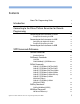
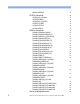
Contents About This Programming Guide Introduction 3 9 Connecting to the Pulse/Pattern Generator for Remote Programming Connecting to the Instrument via GPIB Example for Connecting via GPIB 11 11 12 Connecting to the Instrument via LAN 13 Configuring the Agilent IO Libraries Example for Connecting via LAN 13 Connecting to the Instrument via USB 15 SCPI Commands Reference Common Commands 14 17 19 Standard Settings 21 DIAGnostic Commands 23 :CAL:TIM :DIAG:CHANnel[1|2]:PPERformance DIGital C
:MEASure:PERiod? OUTPut Commands :OUTPut[0|1|2]:DIVider :OUTPut0:SOURce :OUTPut[0|1|2][:STATe] :OUTPut[1|2]:NEG :OUTPut[1|2]:POS :OUTPut:CENTral SOURce Commands [:SOURce]:FUNCtion[:SHAPe] [:SOURce]:FUNCtion:MODe[1|2] [:SOURce]:FREQuency[:CW|:FIXed] [:SOURce]:PHASe[:ADJ][1|2] [:SOURce][:PULSe]:DCYCle[1|2] [:SOURce][:PULSe]:DELay[1|2] [:SOURce][:PULSe]:DESKew[1|2] [:SOURce][:PULSe]:DHOLd[1|2] [:SOURce][:PULSe]:PERiod [:SOURce][:PULSe]:POLarity[1|2] [:SOURce][:PULSe]:WIDTh[1|2] [:SOURce]:PM[1|2] [:SOURce]:PM
:STATus:OPERation :STATus:PRESet :STATus:QUEStionable :STATus:QUEStionable:VOLTage :STATus:QUEStionable:FREQuency :STATus:QUEStionable:MONotony SYSTem Commands :SYSTem:ERRor? :SYSTem:PRESet :SYSTem:SET :SYSTem:VERSion? :SYSTem:COMMunicate:LAN[:SELF]:DHCP :SYSTEM:COMMunicate:LAN[:SELF]:NAME :SYSTem:COMMunicate:LAN[:SELF] :ADDRess :SYSTem:COMMunicate:LAN[:SELF] :SMASk :SYSTem:COMMunicate:LAN[:SELF] :DGATeway :SYSTem:COMMunicate:GPIB[:SELF]:ADDR TRIGger Commands :TRIGger:SOURce :TRIGger:TERM :TRIGger:TERM:ST
Agilent 81133A/81134A Pulse Generator Programming Guide, March 2007
Introduction For controlling the Agilent 81133A/81134A remotely, the instrument provides three different interfaces: • GPIB Using the GPIB connector, the instrument can be controlled from a PC or a UNIX Workstation. • LAN Using the LAN connector, the instrument can be connected to a local area network and can be programmed from a PC. • USB USB is the replacement for GPIB when used on the bench. The language is the same as with GPIB.
Introduction 10 Agilent 81133A/81134A Pulse Generator Programming Guide, March 2007
Connecting to the Pulse/Pattern Generator for Remote Programming The following sections show how to establish the connection between your control PC and the instrument through the available remote interfaces. Connecting to the Instrument via GPIB You can use GPIB connections only for controlling the instrument by means of SCPI commands. To connect to the instrument via GPIB you have to: • Use GPIB cables to connect the instrument to the test environment. • Specify the instrument’s GPIB address.
Connecting to the Pulse/Pattern Generator for Remote Programming Connecting to the Instrument via GPIB Example for Connecting via GPIB The following code example shows how to use the VISA library to connect to the instrument via GPIB. This example queries a GPIB device for an identification string and prints the results. Implementation #include #include
Connecting to the Instrument via LAN Connecting to the Pulse/Pattern Generator for Remote Programming Connecting to the Instrument via LAN For connecting over the LAN, you would do have the following: • Connect the instrument to the LAN physically. • Configure the Agilent IO Libraries on the remote machine. • On the user interface, either specify the LAN address or—if a DHCP server is available—enable the DHCP. The DHCP will automatically set up the LAN connection.
Connecting to the Pulse/Pattern Generator for Remote Programming Connecting to the Instrument via LAN 3 Run IO Config. The IO Config utility (iocfg32.exe) can be found at (default location): C:\Program Files\Agilent\IO Libraries Suite\bin Note that you can also open the IO Config from the Agilent IO Libraries Control icon in the task bar. 4 Edit “inst0” to “lan0”. Select “TCPIP Lan”, then click Edit. This will bring up the list of TCPIP devices already configured.
Connecting to the Instrument via USB Connecting to the Pulse/Pattern Generator for Remote Programming viClose (defaultRM); } Connecting to the Instrument via USB NOTE The control PC must have USB capability for USB connections (Windows NT is not supported). For connecting over the USB, please refer to the Help delivered with the USB driver.
Connecting to the Pulse/Pattern Generator for Remote Programming 16 Connecting to the Instrument via USB Agilent 81133A/81134A Pulse Generator Programming Guide, March 2007
SCPI Commands Reference The following sections describe the SCPI Commands available to program the 81133A/81134A remotely.
SCPI Commands Reference Command Structure Each command description has at least some of the following items: • Full command syntax • Form – Set The command can be used to program the instrument. – Query The command can be used to interrogate the instrument. A question mark (?) is added to the command, the parameters may also change. • Brief description • Parameters • Parameter Suffix The suffixes that may follow the parameter.
Common Commands SCPI Commands Reference Common Commands The following table shows the IEEE 488.2 Common Commands available with the Agilent 81133A/81134A Pulse Generator.
SCPI Commands Reference Commands in the User Interface Common Commands The following figure shows how the IEEE 488.2 Common commands are implemented in the 81133A/81134A user interface.
Common Commands SCPI Commands Reference Standard Settings The following table shows the standard settings (Memory 0).
SCPI Commands Reference 22 Common Commands Parameter SCPI Command Reset Value Range Low Level :VOLT[0|1|2]:LOW -50 mV -2.00 V … +2.95 V High :VOLT[0|1|2]:HIGH 50 mV -1.95 V … +3.00 V Offset :VOLT[0|1|2]:OFFS 0 mV -1.975 V … +2.975 V Amplitude :VOLT[0|1|2] 100 mV 50 mV … 2.00 V Term. Voltage :VOLT[0|1|2]:TERM 0 mV -2.00 V … +3.
DIAGnostic Commands SCPI Commands Reference DIAGnostic Commands The following table shows the Agilent 81133A/81134A Pulse Generator DIAGnostic Commands. Command :CAL:TIM Parameter Description Calibrates the timing system of the instrument :DIAG :CHANnel[1|2] :PPERformance[?] Commands in the User Interface NORMal | FAST Sets/reads channel peak | SMOoth performance The following figure shows how the DIAGnostic commands are implemented in the 81133A/81134A user interface.
SCPI Commands Reference DIAGnostic Commands :CAL:TIM Syntax Form Description NOTE *RST value :CAL:TIM Set Calibrates the timing system of the instrument. Execution of this command can take about 15 minutes. – :DIAG:CHANnel[1|2]:PPERformance Syntax Form Description :DIAG:CHAN[1|2]:PPER[?] Set & Query This command is used to modify the specified transition time of the signal. For the specified transition time, please refer to the Technical Specification delivered on the product CD.
DIGital Commands SCPI Commands Reference DIGital Commands The following table shows the Agilent 81133A/81134A Pulse Generator DIGital commands: Command Parameter Description :DIGital[1|2] [:STIMulus] :PATTern [:DATa][?] , [HEX | Sets/reads data in hexadecimal BIN | DUAL] (default), binary or dual format; this command is for data patterns with maximum 8192 bits :LDATa Sets data in hexadecimal format; this command is for data patterns larger than 8192 bits :LENGth[?] Numeric Sets/read
SCPI Commands Reference Commands in the User Interface DIGital Commands The following figures show how the DIGital commands are implemented in the 81133A/81134A user interface.
DIGital Commands SCPI Commands Reference :DIGital[1|2][:STIMulus]:PATTern[:DATa] Syntax Form Description :DIG[1|2][:STIM]:PATT[:DAT][?] Set & Query This command is used to set or read the pattern data of one of the channels. The minimum length of these patterns is 32 bits, the maximum length is 8192 bits, the granularity is 32 bits. For patterns larger than 8192 bits, see “:DIGital[1|2][:STIMulus]:PATTern:LDATa” on page 29. The data can be written in either hexadecimal, binary or dual format.
SCPI Commands Reference DIGital Commands The is an arbitrary block of program data as defined in IEEE 488.2 7.7.6.2, for example: #181CF1011E, HEX # Start of block 1 Length of the length of the data 8 Length of the data (in bytes) 1CF1011E 32 bits of pattern data HEX Data in hex format #23201001001001001010100101010100110, DUAL # Start of block 2 Length of the length of the data 32 Length of the data (in bytes) 010...
DIGital Commands SCPI Commands Reference :DIGital[1|2][:STIMulus]:PATTern:LDATa Syntax Form Description Parameter :DIG[1|2][:STIM]:PATT:LDAT Set This command is used to program long data patterns in hexadecimal format. The minimum length of these patterns is 128 bits, the maximum length is 12 Mbits, the granularity is 128 bits. Patterns generated with this command are subject to various restrictions (see below). See also “:DIGital[1|2][:STIMulus]:PATTern[:DATa]” on page 27.
SCPI Commands Reference DIGital Commands • The complete pattern is stored temporarily in the instrument. If there are no restrictions to the maximum pattern length regarding frequency and frequency divider, the complete pattern will always be continually emitted. If there are restrictions to the maximum pattern length, the stored pattern will be emitted up to the maximum pattern length and then repeated from the beginning. • The channel mode must be data mode.
DIGital Commands SCPI Commands Reference :DIGital[1|2][:STIMulus]:PATTern:LENGth Syntax Form Description Parameter :DIG[1|2][:STIM]:PATT:LENG[?] Set & Query Defines the length of the data pattern. If the current pattern is longer than the new value for :LENGth, the pattern is truncated. If the current pattern is shorter than the new value for :LENGth, the pattern is lengthened and the new bits are set to ’0’. Numeric Valid values are: 32 … 8192 in steps of 32.
SCPI Commands Reference DIGital Commands Example Set data format to R1. :DIG:SIGN:FORM R1 :DIGital[1|2][:STIMulus]:SIGNal:POLarity Syntax Form Description NOTE Parameter :DIG[1|2][:STIM]:SIGN:POL[?] Set & Query This command is used to program the data polarity for Data and PRBS signals. The 32- bit data pattern is logically inverted, that is, 1 s are replaced with 0 s and vice versa.
DIGital Commands SCPI Commands Reference NOTE This parameter has no influence if the delay control input for the channel is switched on (:PM[1|2] ON). The figure below shows the normal and complement output with the crossover point set to 50% and 70% respectively. 50 % Normal Out 50 % Compl. Out 70 % Normal Out 70 % Compl. Out Parameter Numeric values (in %) in the range of 20 … 80. *RST value 50 Example Set the variable crossover point to 70%.
SCPI Commands Reference DIGital Commands :DIGital[1|2][:STIMulus]:SIGNal: CROSsover:[STATe] Syntax Form Description :DIG[1|2][:STIM]:SIGN:CROS:STAT[?] Set & Query For each channel, the crossover mode of the NRZ signal in PRBS or data pattern mode can be enabled. This is used to artificially close the eye pattern, simulating distortion. If you enabled the variable crossover mode, specify the variable crossover point with “:DIGital[1|2][:STIMulus]:SIGNal: CROSsover:[VALue]” on page 32.
DISPlay Commands SCPI Commands Reference DISPlay Commands The following table shows the Agilent 81133A/81134A Pulse Generator DISPlay commands. Command Parameter Description :DISPlay [:WINDow] [:STATe][?] ON | OFF | 1 | Sets/reads front panel display 0 state :DISPlay[:WINDow][:STATe] Syntax Form Description NOTE :DISP[:WIND][:STAT][?] Set & Query This command is used to turn the front panel display on and off. Switching off the display improves the programming speed of the instrument.
SCPI Commands Reference MEASure Commands MEASure Commands The following table shows the Agilent 81133A/81134A Pulse Generator MEASure commands: Command Parameter Description :MEASure Commands in the User Interface :FREQuency? Read time base frequency :PERiod? Read time base period The following figure shows how the MEASure commands are implemented in the 81133A/81134A user interface.
MEASure Commands SCPI Commands Reference :MEASure:FREQuency? Syntax Form Description :MEAS:FREQ? Query This command is used to measure the operating frequency of the instrument. In internal mode (:TRIGger:SOURce IMMediate) the frequency returned is the measured internal clock frequency (not the programmed value). In external mode (:TRIGger:SOURce EXTernal) the frequency returned is that measured at the Clock Input connector.
SCPI Commands Reference MEASure Commands :MEASure:PERiod? Syntax Form Description :MEAS:PER? Query This command is used to read the operating period of the instrument. In internal mode (:TRIGger:SOURce IMMediate) the period returned is the internal clock period. In external mode (:TRIGger:SOURce EXTernal) the period returned is that measured at the Clock Input connector. If an invalid signal, or no signal, is present at the Clock Input connector, a value of zero is returned.
OUTPut Commands SCPI Commands Reference OUTPut Commands The following table shows the Agilent 81133A/81134A Pulse Generator OUTPut commands.
SCPI Commands Reference Commands in the User Interface OUTPut Commands The following figures show how the DIAGnostic commands are implemented in the 81133A/81134A user interface.
OUTPut Commands SCPI Commands Reference :OUTPut[0|1|2]:DIVider Syntax Form Description :OUTP[0|1|2]:DIV[?] Set & Query This command is used to program the frequency divider parameters of the trigger output (0) and the channel outputs (1, 2). The trigger output frequency is divided only when the trigger output is in Pulse mode (:OUTPut0:SOURce PERiodic). You can program the divider in Data mode (:OUTPut0:SOURce BITstream) but it will have no effect until you select the trigger output to pulse mode.
SCPI Commands Reference OUTPut Commands :OUTPut0:SOURce Syntax Form Description :OUTP0:SOUR[?] Set & Query This command programs the trigger output source mode. • PERiodic This corresponds to Pulse mode on the front panel. The trigger source is the internal clock, and a trigger pulse is generated every clock period, unless the divider parameter has been set to a value other than 1. The trigger signal always has 50% nominal duty cycle. • BITStream This corresponds to the Data mode on the front panel.
OUTPut Commands SCPI Commands Reference :OUTPut[0|1|2][:STATe] Syntax Form Description :OUTP[0|1|2][:STAT][?] Set & Query Switches the trigger output and channel outputs on or off, where 0 is the trigger output. For the two channel outputs, both OUTPUT and OUTPUT are switched simultaneously. In query form, OFF is returned only if both OUTPUT and OUTPUT are off. They can be controlled separately from the front panel, or by adding :POS or :NEG to the command.
SCPI Commands Reference OUTPut Commands :OUTPut[1|2]:POS Syntax Form Description :OUTP[1|2]:POS[?] Set & Query Switches the specified channel OUTPUT on or off. Parameter ON|OFF|1|0 *RST value OFF Example Switch off the channel 1 OUTPUT. :OUTP1:POS OFF :OUTPut:CENTral Syntax Form Description :OUTP:CENT[?] Set & Query Sets or reads the central output settings.
SOURce Commands SCPI Commands Reference SOURce Commands The following table shows the Agilent 81133A/81134A Pulse Generator SOURce commands: Command Parameter Description [:SOURce] :FUNCtion [:SHAPe][?] PATTern| Sets/reads instrument BURSt, | mode RBURSt, , :MODE[1|2][?] PULSe|SQUare| DATa|PRBS Sets instrument main mode :FREQuency [:CW|:FIXed][?] Numeric Sets/reads internal [GHz|MHz|kHz|Hz] | clock frequency MIN|MAX :PHASe [:ADJ][1|2][?] Numeric|MIN|MAX Se
SCPI Commands Reference SOURce Commands Command Parameter Description OFF|ON Sets/reads jitter modulation 25ps|250ps Sets jitter modulation sensitivity [:AMPLitude][?] Numeric [uV|mV|V] |MIN|MAX Sets/reads channel amplitude :OFFSet[?] Numeric [uV|mV|V] |MIN|MAX Sets/reads channel offset :HIGH[?] Numeric [uV|mV|V] |MIN|MAX Sets/reads channel high-level :LOW[?] Numeric [uV|mV|V] |MIN|MAX Sets/reads channel lowlevel :TERM[?] Numeric [uV|mV|V] Sets/reads termination voltage PM[1|2][?] :S
SOURce Commands Commands in the User Interface SCPI Commands Reference The following figures show how the DIAGnostic commands are implemented in the 81133A/81134A user interface.
SCPI Commands Reference SOURce Commands [:SOUR]:VOLT[1|2]:LEV[:IMM]:HIGH[?] [:SOUR]:VOLT[1|2]:LEV[:IMM]:LOW[?] [:SOUR]:VOLT[1|2]:LEV[:IMM]:TERM[?] [:SOUR]:VOLT[1|2]:LIM:STAT[?] [:SOUR]:VOLT[1|2]:LEV[:IMM]:AMPL[?] [:SOUR]:VOLT[1|2]:LEV[:IMM]:OFFS[?] 48 Agilent 81133A/81134A Pulse Generator Programming Guide, March 2007
SOURce Commands SCPI Commands Reference [:SOUR]:VOLT0:LEV[:IMM]:HIGH[?] [:SOUR]:VOLT0:LEV[:IMM]:LOW[?] [:SOUR]:VOLT0:LEV[:IMM]:TERM[?] [:SOUR]:VOLT0:LEV[:IMM]:AMPL[?] [:SOUR]:VOLT0:LEV[:IMM]:OFFS[?] Agilent 81133A/81134A Pulse Generator Programming Guide, March 2007 49
SCPI Commands Reference SOURce Commands [:SOURce]:FUNCtion[:SHAPe] Syntax Form Description Parameter [:SOUR]:FUNC[:SHAP][?] Set & Query Defines the main mode of the signal to be generated (pulse/pattern, burst, or repetitive burst mode).
SOURce Commands SCPI Commands Reference [:SOURce]:FUNCtion:MODe[1|2] Syntax Form Description Parameter [:SOUR]:FUNC:MOD[1|2][?] Set & Query Use this command to set the pattern mode for each channel. The pattern modes specify pulses, clocks, data patterns or PRBS signals. PULSe | SQUare | DATa | PRBS, • SQUare Generates a square wave (clock) of fixed width (50% duty cycle). The frequency of the square wave can optionally be divided by 1, 2, 4, …, 128 with :OUTPut[1|2]:DIVider.
SCPI Commands Reference SOURce Commands [:SOURce]:FREQuency[:CW|:FIXed] Syntax Form Description Parameter Value coupling *RST value Specified limits Example [:SOUR]:FREQ[:CW|:FIX][?] Set & Query This command programs the internal clock frequency, and also selects the internal clock as time base if it is not already selected. Numeric [GHz|MHz|kHz|Hz] | MIN|MAX Period = 1 / Frequency 15.0E6 Hz 15E6 ... 3.35E9 Hz, with overclocking up to 3.35E9 Hz Select the clock with frequency 1.2 GHz. :FREQ 1.
SOURce Commands SCPI Commands Reference [:SOURce]:PHASe[:ADJ][1|2] Syntax Form Description Parameter Parameter Suffix Functional coupling Value coupling Range coupling *RST value [:SOUR]:PHAS[:ADJ][1|2][?] Set & Query This command programs the pulse phase for a channel. Numeric | MIN|MAX DEG or RAD. A parameter without suffix is interpreted as degrees. Programming the pulse phase also executes [:SOURce][:PULSe]:HOLD PHASe so that the pulse phase is held constant when the signal frequency is changed.
SCPI Commands Reference SOURce Commands [:SOURce][:PULSe]:DCYCle[1|2] Syntax Form Description NOTE [:SOUR][:PULS]:DCYC[1|2][?] Set & Query This command programs the duty cycle for a channel. The duty cycle cannot be set: • In direct mode. To query the clock source, see “:TRIGger:SOURce” on page 87. • If signal mode is set to NRZ. To query the signal mode, see “:DIGital[1|2][:STIMulus]:SIGNal:FORMat” on page 31.
SOURce Commands SCPI Commands Reference [:SOURce][:PULSe]:DELay[1|2] Syntax Form Description Parameter Functional coupling Value coupling Range coupling *RST value [:SOUR][:PULS]:DEL[1|2][?] Set & Query This command programs the pulse delay for a channel. Numeric [ps|ns|us|ms|s]|MIN|MAX Programming the pulse delay also executes the [:SOURce][:PULSe]:DHOLD DELays so that the pulse delay is held constant when the signal frequency is changed. Phase = (Delay / Period) * 360 Deskew 0.
SCPI Commands Reference SOURce Commands [:SOURce][:PULSe]:DESKew[1|2] Syntax Form Description [:SOUR][:PULS]:DESK[1|2][?] Set & Query This command programs the deskew for a channel. The deskew allows you to move the zero- point of the delay (and phase) parameter by ± 10 ns. The final delay at the output is Delay + Deskew. Parameter Range coupling *RST value Numeric [ps|ns|us|ms|s]|MIN|MAX Delay, Phase 0.0 Specified limits –10E–9 … 10E–9, but deskew and delay must be within the delay limits.
SOURce Commands SCPI Commands Reference [:SOURce][:PULSe]:PERiod Syntax Form Description Parameter Functional coupling Value coupling Range coupling *RST value Specified limits Instrument limits Example [:SOUR][:PULS]:PER[?] Set & Query This command programs the internal clock period, and also selects the internal clock time base if it has not already been selected.
SCPI Commands Reference SOURce Commands NOTE This is not the same as the :DIGital[1|2][:STIMulus]:SIGNal:POLarity command, which logically inverts the 32- bit data on the channels by swapping 1s with 0s and vice- versa. [:SOURce][:PULSe]:WIDTh[1|2] Syntax Form Description Parameter Functional coupling Value coupling Range coupling *RST value [:SOUR][:PULS]:WIDT[1|2][?] Set & Query Programs the pulse width for a channel.
SOURce Commands SCPI Commands Reference [:SOURce]:PM[1|2] Syntax Form Description [:SOUR]:PM[1|2][?] Set & Query Enables the jitter modulation. Parameter OFF|ON *RST value OFF Example Enable the jitter modulation on channel 1. PM1 ON [:SOURce]:PM[1|2]:SENSitivity Syntax Form Description [:SOUR]:PM[1|2]:SENS Set Sets jitter modulation sensitivity. You now have to apply an external source (–0.5 V … 0.
SCPI Commands Reference SOURce Commands [:SOURce]:VOLTage[0|1|2][:LEVel] [:IMMediate][:AMPLitude] Syntax Form Description [:SOUR]:VOLT[0|1|2][:LEV][:IMM][:AMPL][?] Set & Query Programs the amplitude of the output signal for the trigger output and the channels.
SOURce Commands SCPI Commands Reference [:SOURce]:VOLTage[0|1|2][:LEVel] [:IMMediate]:OFFSet Syntax Form Description [:SOUR]:VOLT[0|1|2][:LEV][:IMM]:OFFS[?] Set & Query Programs the offset of the output signal for the trigger output and the channels. Parameter Numeric [uV|mV|V] |MIN|MAX Value coupling High = Offset + (Amplitude / 2) Low = Offset – (Amplitude / 2) Range coupling *RST value Amplitude Trigger output (0): 0 V Channels 1 and 2: 0 V Specified limits Trigger channel (0): –1.975 V … +2.
SCPI Commands Reference SOURce Commands [:SOURce]:VOLTage[0|1|2][:LEVel] [:IMMediate]:HIGH Syntax Form Description Parameter Value coupling [:SOUR]:VOLT[0|1|2][:LEV][:IMM]:HIGH[?] Set & Query Programs the high- level of the output signal for the trigger output and the channels. Numeric [uV|mV|V] |MIN|MAX Amplitude = High – Low Offset = (High – Low) / 2 Range coupling *RST value Low- level Trigger channel (0): 0.1 V Channels 1 and 2: 0.1 V Specified limits Trigger channel (0): –1.95 … +3.
SOURce Commands SCPI Commands Reference [:SOURce]:VOLTage[0|1|2][:LEVel] [:IMMediate]:LOW Syntax Form Description Parameter Value coupling [:SOUR]:VOLT[0|1|2][:LEV][:IMM]:LOW[?] Set & Query Programs the low- level of the output signal for the trigger output and the channels. Numeric [uV|mV|V] |MIN|MAX Amplitude = High – Low Offset = (High – Low) / 2 Range coupling *RST value High- level Trigger channel (0): 0.0 V Channels 1 and 2: 0.0 V Specified limits Trigger channel (0): –2.0 … +2.
SCPI Commands Reference SOURce Commands [:SOURce]:VOLTage[0|1|2][:LEVel] [:IMMediate]:TERM Syntax Form Description [:SOUR]:VOLT[0|1|2][:LEV][:IMM]:TERM[?] Set & Query Programs the termination voltage of the output signal for the trigger output and the channels. Parameter Numeric [uV|mV|V] *RST value Trigger output (0): 0.0 V Channels 1 and 2: 0.0 V Specified limits Trigger output (0): –2.0 V … +3.0 V Channels 1 and 2: –2.0 V … +3.0 V Example Set Channel 1 termination voltage to 1 V.
SOURce Commands SCPI Commands Reference [:SOURce]:VOLTage[1|2]:LIMit:OFFSet? Syntax Form Description *RST value Example [:SOUR]:VOLT[1|2]:LIM:OFFS? Query This command reads the current setting of the offset limit. The result is only valid if “Limit to current levels” output mode is currently on ([:SOURce]:VOLTage[1|2]:LIMit:STATe ON). 0 mV Read Channel 1 offset limit.
SCPI Commands Reference SOURce Commands [:SOURce]:VOLTage[1|2]:LIMit:STATe Syntax Form Description [:SOUR]:VOLT[1|2]:LIM:STAT[?] Set & Query Switches the “Limit to current values” output mode on or off. When you switch on Limited output mode the current high- level and low- level parameters are taken as limit values restricting the available ranges of all output- level parameters. You cannot program the output- levels beyond these temporary limits, until you switch off Limited output mode.
Status Handling Commands SCPI Commands Reference Status Handling Commands The IEEE 488.2 specification requires status registers that contain information about the instrument’s hardware and firmware. For the Agilent 81133A/81134A Pulse Generator, the status registers have the following structure: :QUEStionable:VOLTage (not used) 0 1 2 + 15 :QUEStionable:FREQuency Frequency Range PLL Unlocked Ext. Ref.
SCPI Commands Reference Status Handling Commands The following table shows the Agilent 81133A/81134A Pulse Generator Status Handling Commands: Command Parameter Description :STATus :OPERation [:EVENt]? Reads operation event register :CONDition? Reads operation condition register :ENABle[?] Numeric Sets/reads operation enable register :NTRansition[?] Numeric Sets/reads operation negativetransition filter :PTRansition[?] Numeric Sets/reads operation positivetransition filter :PRESet Clears
Status Handling Commands SCPI Commands Reference Command Parameter Description :NTRansition[?] Numeric Sets/reads questionable frequency negative-transition register :PTRansition[?] Numeric Sets/reads questionable frequency positive-transition register :MONotony [:EVENt]? Reads questionable monotony event register :CONDition? Reads questionable monotony condition register :ENABle[?] Numeric Sets/reads questionable monotony enable register :NTRansition[?] Numeric Sets/reads questionable m
SCPI Commands Reference Status Handling Commands :STATus:OPERation This command tree accesses the OPERation status group. The OPERation status group is not used by the Agilent 81133A/81134A Pulse Generator, therefore this command tree is redundant.
Status Handling Commands SCPI Commands Reference :STATus:QUEStionable This command tree accesses the QUEStionable status group. The QUEStionable status group contains the summary bits from the QUEStionable:VOLTage, :FREQuency and MONotony status group. The following commands are used to access the registers within the status group. :STATus:QUEStionable[:EVENt]? Syntax Form Description :STAT:QUES[:EVEN]? Query Reads the event register in the QUEStionable status group.
SCPI Commands Reference Status Handling Commands Parameter Numeric *RST value – Specified limits 0 … 32767 :STATus:QUEStionable:NTRansition Syntax Form Description NOTE :STAT:QUES:NTRansition[?] Set & Query Sets or queries the negative- transition register in the QUEStionable status group. The Agilent 81133A/81134A Pulse Generator does not use the transition registers of the QUEStionable status group, therefore, this command is redundant.
Status Handling Commands SCPI Commands Reference :STATus:QUEStionable:VOLTage This command tree accesses the QUEStionable:VOLTage status group. The QUEStionable:VOLTage status group monitors the currently programmed output voltage levels against their specified ranges. The following commands are used to access the registers within the status group.
SCPI Commands Reference Status Handling Commands Specified limits 0 … 32767 :STATus:QUEStionable:VOLTage:NTRansition Syntax Form Description :STAT:QUES:VOLT:NTR[?] Set & Query Sets or queries the negative- transition register in the QUEStionable:VOLTage status group.
Status Handling Commands SCPI Commands Reference :STATus:QUEStionable:FREQuency[:EVENt]? Syntax Form Description :STAT:QUES:FREQ[:EVEN]? Query Reads the event register in the QUEStionable:FREQency status group. Parameter – *RST value – :STATus:QUEStionable:FREQuency:CONDition? Syntax Form Description :STAT:QUES:FREQ:COND? Query Reads the condition register in the QUEStionable:FREQency status group.
SCPI Commands Reference Status Handling Commands :STATus:QUEStionable:FREQuency:NTRansition Syntax Form Description :STAT:QUES:FREQ:NTR[?] Set & Query Sets or queries the negative- transition register in the QUEStionable:FREQency status group. Parameter Numeric *RST value – Specified limits 0 … 32767 :STATus:QUEStionable:FREQuency:PTRansition Syntax FormForm Description :STAT:QUES:FREQ:PTR[?] Set & Query Sets or queries the positive- transition register in the QUEStionable:FREQency status group.
Status Handling Commands SCPI Commands Reference When a parameter range change occurs, the corresponding bit in the QUEStionable:MONotony status event register is set to indicate that the output signal may not vary monotonically with the programmed parameter value. The following commands are used to access the registers within the status group.
SCPI Commands Reference Status Handling Commands :STATus:QUEStionable:MONotony:ENABle Syntax Form Description :STAT:QUES:MON:ENAB[?] Set & Query Sets or queries the enable register in the QUEStionable:MONotony status group. Parameter Numeric *RST value – Specified limits 0 … 32767 :STATus:QUEStionable:MONotony:NTRansition Syntax Form Description NOTE :STAT:QUES:MON:NTR[?] Set & Query Sets or queries the negative- transition register in the QUEStionable:MONotony status group.
SYSTem Commands SCPI Commands Reference NOTE The Agilent 81133A/81134A Pulse Generator does not use the transition registers of the QUEStionable:MONotony status group, therefore, this command is redundant.
SCPI Commands Reference SYSTem Commands Command Parameter Description :HADDRess String Set/read host LAN address for the instrument. This setting is important for FTP transfer :NAME alphanumeric Sets the LAN name for the instrument :DHCP 1|0|ON|OFF Enables/disables DHCP configuration Numeric Sets/reads GPIB bus No.
SYSTem Commands SCPI Commands Reference :SYSTem:ERRor? Syntax Form Description :SYST:ERR? Query This command is used to read the Agilent 81133A/81134A Pulse Generator error queue. The Agilent 81133A/81134A Pulse Generator error queue can store up to 32 error codes on a firstin- first- out basis. When you read the error queue, the error number and associated message are put into the instrument’s output buffer. If the error queue is empty, the value 0 is returned, meaning No Error.
SCPI Commands Reference SYSTem Commands :SYSTem:SET Syntax :SYST:SET[?] Form Set & Query Description In query form, the command reads a block of data containing the instrument’s complete setup. The setup information includes all parameter and mode settings, but does not include the contents of the instrument setting memories, the status group registers or the :DISPlay[:WINDow][:STATe]. The data is in a binary format, not ASCII, and cannot be edited.
SYSTem Commands SCPI Commands Reference :SYSTem:COMMunicate:LAN[:SELF]:DHCP Syntax Form Description :SYST:COMM:LAN[:SELF]:DHCP Set Enables/disables the DHCP. • DHCP enabled If DHCP is enabled, the instrument will request its own LAN settings from the network. You only need to specify the LAN name with “:SYSTEM:COMMunicate:LAN[:SELF]:NAME” on page 83.
SCPI Commands Reference SYSTem Commands :SYSTem:COMMunicate:LAN[:SELF] :ADDRess Syntax Form Description NOTE :SYST:COMM:LAN[:SELF]:ADDR[?] Set & Query Sets the instrument's IP address. This parameter must only be set if DHCP is not available. See “:SYSTem:COMMunicate:LAN[:SELF]:DHCP” on page 83. Parameter String ... in quotes, where is in the range 1 … 255. *RST value – Example :SYST:COMM:LAN:ADDR "150.215.17.
SYSTem Commands SCPI Commands Reference :SYSTem:COMMunicate:LAN[:SELF] :DGATeway Syntax Form Description NOTE :SYST:COMM:LAN[:SELF]:DGAT[?] Set & Query Sets the instrument’s gateway. This parameter must only be set if DHCP is not available. See “:SYSTem:COMMunicate:LAN[:SELF]:DHCP” on page 83. Parameter String ... in quotes, where is in the range 1 … 255. *RST value – Example :SYST:COMM:LAN:DGAT "150.215.001.
SCPI Commands Reference TRIGger Commands TRIGger Commands The following table shows the Agilent 81133A/81134A Pulse Generator TRIGger Commands: Command Parameter Description :SOURce[?] IMMediate|EXTernal | REFerence| IDIRect| EDIRect Sets/reads timebase mode internal, external, external 10 MHz reference, internal direct and external direct :TERM[?] Numeric [uV|mV|V] Sets/reads termination voltage :TERMSTATe[?] ON|OFF Sets/reads termination state.
TRIGger Commands SCPI Commands Reference :TRIGger:SOURce Syntax Form Description :TRIG:SOUR[?] Set & Query This command is used to switch the timebase mode between Internal (IMMediate) and External (EXTernal). With :TRIGger:SOURce IMMediate (internal timebase) the frequency (or period) is controlled with the [:SOURce]:FREQuency (or [:SOURce][:PULSe]:PERiod) command.
SCPI Commands Reference TRIGger Commands – EDIRect Allows you to vary the frequency of the external clock signal in the range of one octave. Range switching occurs at the following frequency values: • 1680 MHz • 840 MHz • 420 MHz • 210 MHz • 105 MHz • 51.5 MHz • 25.75 MHz These values are based on 1680 MHz, subject to the frequency divider. *RST value Example IMMediate Select the external timebase mode.
TRIGger Commands SCPI Commands Reference :TRIGger:TERM:STATE[?] Syntax Form Description :TRIG:TERM:STATE[?] Set & Query Defines whether the external clock input connector (Clock In) is AC or DC terminated. Parameter ON|OFF where ON = DC and OFF = AC terminated. *RST value OFF Example Set the coupling of the external clock input connector to DC.
SCPI Commands Reference ARM Commands ARM Commands The following table shows the Agilent 81133A/81134A Pulse Generator ARM Commands: Command Parameter :ARM Description External start input [:SEQuence] [:LAYer] :LEVel Numeric[mV|V] Sets the trigger threshold :SLOPe POSitive|NEGative Trigger set to leading/trailing edge of external signal :SOURce IMMediate| MANual|EXTernal Sets the start input to disabled/manual (by key)/external started :TERM[?] Numeric [mV|V] Sets/reads termination voltage
ARM Commands SCPI Commands Reference :ARM[:SEQuence][:LAYer]:LEVel Syntax Form Description NOTE Parameter :ARM[:SEQ][:LAY]:LEV Set & Query Specifies the threshold voltage for the external start signal. The threshold can only be specified if the external start mode is selected (“:ARM:SOURce EXT”). Numeric [mV|V] Specified limits –2 V … 3.0 V Absolute limits –2.0 V … 3.0 V *RST value Example 100 mV Sets the threshold voltage to 2.0 V. :ARM:LEV 2.
SCPI Commands Reference ARM Commands :ARM[:SEQuence][:LAYer]:SLOPe Syntax Form Description NOTE Parameter :ARM[:SEQ][:LAY]:SLOP Set & Query Specifies whether the signal is generated at the rising or falling edge of the external start signal. The threshold can only be specified if the external start mode is selected (“:ARM:SOURce EXT”). POSitive|NEGative • POSitive The signal is generated at the rising edge. • NEGative The signal is generated at the falling edge.
ARM Commands SCPI Commands Reference :ARM[:SEQuence][:LAYer]:SOURce Syntax Form Description Parameter :ARM[:SEQ][:LAY]:SOUR Set & Query Specifies when the generated signal is output immediately, by manual start or depending on an external signal at the Start In connector. IMMediate|MANual|EXTernal The instrument provides the following start modes: • IMMediate The generated signal is always available at the outputs (assumed that the outputs are enabled).
SCPI Commands Reference ARM Commands :ARM[:SEQuence][:LAYer]:TERM Syntax Form Description Parameter Specified limits *RST value Example :ARM[:SEQ][:LAY]:TERM[?] Set & Query Sets/reads the termination voltage for the start input signal. Numeric [mV|V] –2.0 V … 3.0 V 0 mV Set the termination voltage to 1 V. :ARM:TERM 1V :ARM[:SEQuence][:LAYer][:STARt] Syntax Form Description NOTE :ARM[:SEQ][:LAY][STAR] Event Puts the instrument in armed mode.
ARM Commands SCPI Commands Reference :ARM[:SEQuence][:LAYer]:STOP Syntax Form Description :ARM[:SEQ][:LAY]:STOP Event Deactivates the armed mode for the instrument.
SCPI Commands Reference 96 ARM Commands Agilent 81133A/81134A Pulse Generator Programming Guide, March 2007
Troubleshooting This chapter provides basic troubleshooting tips that you can use if the instrument is not performing as expected. Error Generated The instrument generates error messages as follows: -221:Settings conflict:String describing the error The string describing the error could be one of the following: • "divider of channel [1|2] leads to a frequency below minimum frequency" This occurs if the frequency below one of the channels is set below the minimum (15 MHz).
Troubleshooting • "delay of channel [1|2] below minimum" May happen: – If the frequency is decreased and the channel is in phase mode, or – if the square mode is switched from square to another mode, or – if clock mode is switched from internal/external direct to a none direct mode.
Troubleshooting – If the trigger amplitude is increased, or – if the offset is decreased. • "low level of channel [1|2] is below minimum" May happen: – If the channel amplitude is increased, or – if the offset is decreased. • "high level of trigger exceeds maximum" May happen: – If the trigger amplitude is increased, or – if the offset is increased. • "high level of channel [1|2] exceeds maximum" May happen: – If the channel amplitude is increased, or – if the offset is increased.
Troubleshooting 100 Agilent 81133A/81134A Pulse Generator Programming Guide, March 2007
Differences between the 8133A and the 81133A/81134A This chapter shows you how to adapt a program written for the 8133A 3 GHz Pulse Generator to the new 81133A/81134A instrument.
Differences between the 8133A and the 81133A/81134A SYSTem Commands “:SYSTem:COMMunicate:LAN[:SELF]:DHCP” on page 83 “:SYSTEM:COMMunicate:LAN[:SELF]:NAME” on page 83 “:SYSTem:COMMunicate:LAN[:SELF] :ADDRess” on page 84 “:SYSTem:COMMunicate:LAN[:SELF] :SMASk” on page 84 “:SYSTem:COMMunicate:LAN[:SELF] :DGATeway” on page 85 “:SYSTem:COMMunicate:GPIB[:SELF]:ADDR” on page 85 TRIGger Commands “:TRIGger:TERM” on page 88 “:TRIGger:TERM:STATE[?]” on page 89 ARM Commands “:ARM[:SEQuence][:LAYer]:LEVel” on page 91
Differences between the 8133A and the 81133A/81134A Obsolete Commands The following tables list all commands that no longer exist for the 81133A/81134A pulse/pattern generator: DIAGnostic Commands :DIAG:CHANnel[1|2]:CABLecomp :DIAG:CHANnel[1|2]:SMOothshape :DIAG:TEMPCAL MEASure Commands :MEASure:TEMPerature? SOURce Commands [:SOURce]:FUNCtion:SOURce[?] [:SOURce]:FUNCtion:BURSTcount [:SOURce]:FUNCtion:RBURSTcount SYSTem Commands :SYSTem:KEY[?] TRIGger Commands :TRIGger:[START] :TRIGger:STOP Agilent 81
Copyright Agilent Technologies 2007 Printed in Germany March 2007 5988-7402EN sA