S Agilent 81101A 50 MHz Pulse Generator Quick Start Guide S1
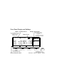
Front Panel Display and Softkeys Mode / Parameter Area Use the CURSOR keys to move the entry focus to a mode, parameter format, or parameter value Use the KNOB to select a mode or modify parameters and formats Entry Focus Press ENTER or a UNIT key to confirm parameter changes Per 1.000µ µs Normal Delay Width LeadE TraiE Modify / Enter Area OFF 1 MODIFY 0ps Offset +0.0mV *OFF 100.0ns Amplit 1.00V ON 5.00ns 50Ω Ω into 50.
Quick Start Guide Agilent 81101A 50 MHz Pulse Generator Part No. 81101-91020 Printed in Germany March 2000 Edition 1.
Notice Notice Copyright 1998 Agilent Technologies 1998, 2000. All rights reserved. No part of this manual may be reproduced in any form or by any means (including electronic storage and retrieval or translation into a foreign language) without prior agreement and written consent from Agilent Technologies Inc. as governed by United States and international copyright laws. Notice The material contained in this document is subject to change without notice.
Notice Agilent Technologies warrants that its software and firmware designated by Agilent Technologies for use with an instrument will execute its programming instructions when properly installed on that instrument. Agilent Technologies does not warrant that the operation of the instrument software, or firmware, will be uninterrupted or error free.
Safety Summary Safety Summary The following general safety precautions must be observed during all phases of operation of this instrument. Failure to comply with these precautions or with specific warnings elsewhere in this manual violates safety standards of design, manufacture, and intended use of the instrument. Agilent Technologies Inc. assumes no liability for the customer's failure to comply with these requirements.
Safety Summary Ground the Instrument To minimize shock hazard, the instrument chassis and cover must be connected to an electrical protective earth ground. The instrument must be connected to the ac power mains through a grounded power cable, with the ground wire firmly connected to an electrical ground (safety ground) at the power outlet.
Safety Summary Safety Symbols Caution (refer to accompanying documents) Protective earth (ground) terminal In the manuals: WA RN I NG The WARNING sign denotes a hazard. It calls attention to a procedure, practice, or the like, which, if not correctly performed or adhered to, could result in personal injury. Do not proceed beyond a WARNING sign until the indicated conditions are fully understood and met. CA UT IO N The CAUTION sign denotes a hazard.
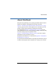
About this Book About this Book This quick start guide helps you to quickly get familiar with the features and the user interface of the Agilent 81101A Pulse Generator. Chapter 1 Introducing the Agilent 81101A Pulse Generator on page 15 gives a general overview of the Agilent 81101A, its features, the user interface, and the steps required for operating the instrument.
About this Book Conventions Used in this Book This book uses certain conventions to indicate elements of the Agilent 81101As user interface. The following table shows some examples: Softkeys Press the MODE/TRG softkey to access the Mode/ Trigger screen. Hardkeys Press the MORE key to switch to the alternative softkey layout. Alternate Keys Press SHIFT + 0 (ON/OFF) to switch on the output. The alternate key labelwhich is selected by pressing the SHIFT keyis given in parentheses.
Contents Notice ......................................................................................... 4 Safety Summary ......................................................................... 6 About this Book ......................................................................... 9 Chapter 1 Introducing the Agilent 81101A Pulse Generator What you can do with the Agilent 81101A ............................ 16 The Front Panel .......................................................................
Contents Chapter 3 Using the Agilent 81101A The Mode/Trigger Screen ....................................................... 44 Overview ................................................................................................. 44 Continuous Pulses Mode ...................................................................... 46 Continuous Burst Mode ........................................................................ 47 Triggered Pulses Mode .........................................................
Contents Power Requirements ............................................................... 80 Power Cable ............................................................................. 82 Ventilation Requirements ....................................................... 83 Thermal Protection ............................................................................... 83 Battery ..................................................................................... 84 Battery Replacement .....................
Contents xiv
1 1Introducing the Agilent 81101A Pulse Generator The purpose of the introduction chapter is to give a general overview of the Agilent 81101A. The main features and use models are described in What you can do with the Agilent 81101A on page 16. Operating the instrument via the front panel user interface is described in The Front Panel on page 18 and Operating the Agilent 81101A on page 20. Help is Available on page 27 shortly introduces the Agilent 81101As on-line help system.
Introducing the Agilent 81101A Pulse Generator What you can do with the Agilent 81101A What you can do with the Agilent 81101A This section introduces the basic features and use models of the Agilent 81101A Pulse Generator. Basic Features The Agilent 81101A is a single-channel pulse generator with variable transition times.
Introducing the Agilent 81101A Pulse Generator What you can do with the Agilent 81101A Automated Testing The Agilent 81101A features an GP-IB/SCPI-conform command structure for all features. Using this programming interface, the instrument can be easily integrated into all phases of test system development such as planning rack integration and test program generation. Programs designed for the Agilent 81101A are compatible with all other models of the Agilent 81100 family.
Introducing the Agilent 81101A Pulse Generator The Front Panel The Front Panel When used for benchtop testing, the instrument is mainly operated from the front panel. Special Function Keys Front Panel Switch Softkeys MORE Key Data Entry Keys Cursor Keys Rotary Knob Inputs and Outputs The front panel switch is used to switch on and off the instrument. NOTE When the front panel switch is off, the instrument is in standby mode.
Introducing the Agilent 81101A Pulse Generator The Front Panel The major inputs and outputs of the instrument are available at the front panel: The external input (EXT INPUT) can be used to connect an external arming source (triggered or gated modes), or to perform pulse recovery (external width mode). For details, please refer to The Mode/Trigger Screen on page 44. The strobe output (STROBE OUT) provides a signal indicating the duration of a burst.
Introducing the Agilent 81101A Pulse Generator Operating the Agilent 81101A Operating the Agilent 81101A This section guides you through the first steps when operating the Agilent 81101A via the user interface. NOTE For information on operating the Agilent 81101A via remote control, please refer to the Reference Guide, part number 81101-91021. Switching On the Instrument After switching on the instrument the display indicates that the instrument selftest is running.
Introducing the Agilent 81101A Pulse Generator Operating the Agilent 81101A The Basic Screens The major parameters for pulse generation can be set up in only two screens. The Mode/Trigger screen allows you to set the fundamental operating and trigger modes with respect to the signal required.
Introducing the Agilent 81101A Pulse Generator Operating the Agilent 81101A The Output screen allows you to specify timing and level parameters for the signal to be generated. µs Normal Per 1.000µ Delay Width LeadE TraiE 1 MODIFY 0ps Offset +0.0mV *OFF 100.0ns Amplit 1.00V ON Ω into 50.0Ω Ω 5.00ns 50Ω =LeadE MODE/TRG Press the OUTPUT softkey to access this screen.
Introducing the Agilent 81101A Pulse Generator Operating the Agilent 81101A Adjusting Parameters Adjusting parameters within a screen, requires two steps: selecting the parameter adjusting its value Some parameters allow different formats of their values. For example, the pulse width can be displayed and entered as an absolute value, as duty cycle (percentage of the period), or as the delay of the trailing edge.
Introducing the Agilent 81101A Pulse Generator Operating the Agilent 81101A When changing the 3 Turn the knob to select DUTYCYCLE. parameter format, The selected setting is indicated by an *. the instrument 4 Move the cursor to the right to select the duty cycle value. automatically recalculates the 5 Use the data entry keys or the knob to enter the required value: 50. value. 6 Press the ENTER key to confirm your selection. Per 1.000µ µs Normal Delay DtyCyc LeadE TraiE OFF 1 MODIFY 0.0ps Offset +0.
Introducing the Agilent 81101A Pulse Generator Operating the Agilent 81101A Advanced Procedures The following features can be used to make operation more comfortable. Selecting parameters SHIFT Most keys of the front panel have an additional function. The SHIFT key provides fast access to the additional functions of the data entry keys and the special function keys. For example, it is possible to quickly access the pulse width parameter by pressing SHIFT + 6 (WIDTH).
Introducing the Agilent 81101A Pulse Generator Operating the Agilent 81101A Switching the Output On and Off When you switch the instrument on, the output is switched off to protect the device under test. The LED indicator next to the output connector indicates the output state. ON/OFF 0 To switch the output on or off either press SHIFT + 0 (ON/OFF), or move the cursor to the ON/OFF parameter in the Output screen and select the appropriate value by turning the knob.
Introducing the Agilent 81101A Pulse Generator Help is Available Help is Available Whenever you are in doubt or the instrument signals warnings or errors, press the HELP key. Help If there are no warnings or errors pending, pressing the HELP key displays information on the currently selected parameter, the parameter help.
Introducing the Agilent 81101A Pulse Generator The Rear Panel The Rear Panel The rear panel always provides two connectors: The input connector for external frequency reference (CLOCK/REF INP.). This input can be used if a higher frequency accuracy is required, or if you need frequency locking. The GP-IB connector providing the interface for remote control. The following figure shows the rear panel view with the option UN2.
2 2Getting Started The intention of this chapter is to give the necessary steps to set up generic signals for first-time users of the Agilent 81101A. This chapter provides examples for the following types of signals: “Setting Up a Clock Signal” on page 30 “Setting Up a Pulse Signal” on page 35 “Setting Up a Burst Signal” on page 39 At the end of each example, the required set of device commands is listed to provide programming examples.
Getting Started Setting Up a Clock Signal Setting Up a Clock Signal Task Set up a continuous clock signal with 25 MHz frequency with PLL accuracy, a duty cycle of 50 %, 6 ns transition times, a high level of 2.5 V and low level of 0 V. Duty Cycle = 50 % 2.5 V 0.0 V f = 25 MHz Instructions To set the operating mode and trigger mode as required: 1 Reset all parameters and modes by pressing SHIFT + STORE (RECALL) + 0. 2 Press the MODE/TRG softkey to enter the Mode/Trigger screen.
Getting Started Setting Up a Clock Signal To set the timing parameters as required: 1 Press the OUTPUT softkey to enter the Output screen. 2 Press SHIFT + 0 (ON/OFF). This turns on the Output and activates the internal error check to detect parameter conflicts. 3 Move the entry focus to PER and turn the knob to select FREQ. 4 Move the entry focus to the right (to the frequency entry field) and enter a value of 25 MHz by pressing 2 + 5 + MICRO/MEGA.
Getting Started Setting Up a Clock Signal 1 ON LeadEdge1 6.00 ns MODE/TRG OUTPUT LIMITS TRG-LEV You can modify the parameter displayed in the Modify/Enter area, and immediately check how your changes affect the signal. Use the cursor keys to switch to another parameter. 9 Press SHIFT + MORE (GRAPH) to return to the textual screen. To set the level parameters as required: 1 Move the entry focus to OFFSET/AMPLITUDE and turn the knob to select HIGH-LOW.
Getting Started Setting Up a Clock Signal Here is the signal as displayed on an Agilent 54810A Infinium oscilloscope. Use the generator’s TRIGGER OUT to trigger the scope.
Getting Started Setting Up a Clock Signal Programming Example If you want to include this clock signal in your GP-IB program, use the following command lines. The comment lines starting with a # are not required. # Reset the instrument to start from a defined, default status. *RST # Switch off the automatic display update to increase programming # speed. :DISPlay OFF # Internal PLL has to be set as period source.
Getting Started Setting Up a Pulse Signal Setting Up a Pulse Signal Task Set up a continuous pulse signal with 50 ns period, a pulse width of 30 ns, a leading edge of 6 ns, a trailing edge of 10 ns, an amplitude of 3.3 V and an offset of 1.65 V (high level 3.3 V, low level 0.0 V). Pulse Width = 30 ns 3.3 V 50 % 0.0 V Period = 50 ns Instructions To set the operating mode and trigger mode as required: 1 Reset all parameters and modes by pressing SHIFT + STORE + 0.
Getting Started Setting Up a Pulse Signal To set the timing parameters as required: 1 Press the OUTPUT softkey to enter the Output screen. 2 Switch on the output. 3 Enter a period of 50 NS. A warning is shown, which you may ignore, because the parameter conflict will be solved in the next steps. 4 Enter a pulse width of 30 NS. 5 Enter 6 NS for the leading edge. 6 For the trailing edge, select ABSOLUTE and enter a value of 10 NS. Per 50.00ns Normal Delay Width LeadE TraiE ON 1 0.0ps Offset +0.0mV 30.
Getting Started Setting Up a Pulse Signal Here is the figure as displayed on the Agilent 54810A Infinium oscilloscope. Use the generator’s TRIGGER OUT to trigger the scope.
Getting Started Setting Up a Pulse Signal Programming Example If you want to include this pulse signal in your GP-IB program, use the following command lines. The comment lines starting with a # are not required. # Reset the instrument to start from a defined, default status. *RST # Switch off the automatic display update to increase programming # speed.
Getting Started Setting Up a Burst Signal Setting Up a Burst Signal Task Set up a burst signal with a burst repetition of 2 µs. Each burst consists of two double-pulses at a period of 500 ns. The pulse width is 100 ns, the delay between the two pulses of a double-pulse is 200 ns. The levels are 2 Vpp amplitude and 0 V offset.
Getting Started Setting Up a Burst Signal TRIGGERED BURSTS OF 2-Double-Pulses at Out1 Pulse-Period: internal Osc Trg'd by: PLL -> Per 2.000 µs MODE/TRG OUTPUT MODIFY 2.000 µs LIMITS TRG-LEV To set the timing parameters as required: 1 Press the OUTPUT softkey to enter the Output menu. 2 Switch on the Output. 3 Enter a pulse period of 500 NS. 4 Enter a double-pulse delay (DBLDEL) of 200 NS. To set the level parameters as required: 1 Enter an amplitude of 2.00 V. Per 500.
Getting Started Setting Up a Burst Signal The following figure shows the signals as displayed on the Agilent 54810A Infinium Oscilloscope if you connect OUTPUT to channel 1, STROBE OUT to channel 2, and use the generator’s TRIGGER OUT to trigger the scope.
Getting Started Setting Up a Burst Signal Programming example If you want to include this burst signal in your GP-IB program use the following command lines. The comment lines starting with a # are not required. # Reset the instrument to start from a defined, default status. *RST # Switch off the automatic display update to increase programming # speed. :DISPlay OFF # Set the instrument to burst mode by selecting a burst count # of 2. Choose double pulses.
3 3Using the Agilent 81101A This chapter provides complete reference information for using the Agilent 81101A by means of the user interface screens. Each screen is described in detail. To access the individual screens, use the softkeys below the screen.
Using the Agilent 81101A The Mode/Trigger Screen The Mode/Trigger Screen This section describes the Mode/Trigger screen, starting with an overview of the available parameter combinations, followed by detailed descriptions of each combination. Overview To access the Mode/Trigger screen, press the MODE/TRG softkey. The following figure shows a typical Mode/Trigger screen, where the individual parameters are indicated. The parameter combinations are listed in the table on the next page.
Using the Agilent 81101A The Mode/Trigger Screen Furthermore, you can specify the pulse and trigger sources. The following table provides a list of possible parameter combinations. The rows refer to the numbers in the figure. ➀ Trigger Mode Continuous ➁ Pulse Mode Pulses ➂ Pulse Type Single/Double ➃ Length ➄ Period Source ➅ Arming Source Triggered Burst Burst Single/Double 265536 Pulses Ext. Width Burst Single/Double 265536 internal Osc. internal PLL CLK-IN 265536 internal Osc.
Using the Agilent 81101A The Mode/Trigger Screen Continuous Pulses Mode The following figure shows typical timings for trigger mode CONTINUOUS and pulse mode PULSES. Period Period Source int Osc, int PLL or Ext Clock OUTPUT Single Pulse OUTPUT Double Pulse TRIGGER OUT Characteristics Pulse periods are generated continuously. You can select single pulses or double pulses per pulse period.
Using the Agilent 81101A The Mode/Trigger Screen Continuous Burst Mode The following figure shows typical timings for trigger mode CONTINUOUS and pulse mode BURST. Burst of 3 Period Period Source int Osc, int PLL or Ext Clock OUTPUT Single Pulse OUTPUT Double Pulse TRIGGER OUT STROBE OUT 1st period Characteristics last period A burst of pulse periods is repeated continuously. You can select the number of pulse periods per burst in the range of 265536.
Using the Agilent 81101A The Mode/Trigger Screen Triggered Pulses Mode The following figure shows typical timings for trigger mode TRIGGERED and pulse mode PULSES. The pulses are triggered by the rising edge of the arming source.
Using the Agilent 81101A The Mode/Trigger Screen In contrast to the previous figure, this figure shows a timing diagram where the pulses are triggered by both rising and falling edges of the arming source.
Using the Agilent 81101A The Mode/Trigger Screen Triggered Burst Mode The following figures show typical timings for trigger mode TRIGGERED and pulse mode BURST. The bursts are triggered by the rising edge of the arming source. For the first example, the synchronously triggerable internal oscillator is used to source the period. Trg'd by: Oscillator starts synchronously ARMING SOURCE (Trg'd by:) EXT INPUT or MAN Key or PLL PERIOD SOURCE Period Burst of 3 internal Osc.
Using the Agilent 81101A The Mode/Trigger Screen TRIGGER OUT marks each pulse period. STROBE OUT rises at the start of the first pulse period in a burst and falls at the start of the last pulse period. For the second example, either the internal PLL or an external CLK-IN are used to source the periodboth cannot be triggered synchronously.
Using the Agilent 81101A The Mode/Trigger Screen Gated Pulses Mode The following figures show typical timings for trigger mode GATED and pulse mode PULSES. For the first example, the synchronously triggerable internal oscillator is used to source the period.
Using the Agilent 81101A The Mode/Trigger Screen For the second example, either the internal PLL or an external CLK-IN are used to source the periodboth cannot be triggered synchronously.
Using the Agilent 81101A The Mode/Trigger Screen Gated Burst Mode The following figures show typical timings for trigger mode GATED and pulse mode BURST. For the first example, the synchronously triggerable internal oscillator is used to source the period. Gated by: Oscillator starts synchronously ARMING SOURCE (Gated by:) EXT INPUT or MAN Key Burst of 3 PERIOD SOURCE Period internal Osc.
Using the Agilent 81101A The Mode/Trigger Screen For the second example, either the internal PLL or an external CLK-IN are used to source the periodboth cannot be triggered synchronously. Gated by: ARMING SOURCE PLL/CLK-IN NOT Synchronous to EXT INPUT DELAY = n * Period, 1 < n ≤ 2 (Gated by:) EXT INPUT or MAN Key Burst of 3 Period PERIOD SOURCE internal PLL.
Using the Agilent 81101A The Output Screen The Output Screen The Output screen shows both timing and level parameters on one screen. To access the Output screen, press the OUTPUT softkey. Timing Parameters You can use the left part of the Output screen to view and control the pulse timing parameters. Per Delay Width LeadE TraiE 1.000µ µs Normal OFF 1 MODIFY 0ps Offset +0.0mV *Period 100.0ns Amplit 1.00V Frequency 5.00ns 50Ω Ω into 50.
Using the Agilent 81101A The Output Screen When you press SHIFT + MORE (GRAPH) while one of the timing parameters is selected, you will see a graphical representation of the timing parameters. The currently selected parameter is displayed in the Modify/ Enter area and is indicated by dashed or bold lines in the graphical display. 1 OFF Width1 100.0 ns MODE/TRG OUTPUT LIMITS 1 OFF TRG-LEV PERIOD 1.
Using the Agilent 81101A The Output Screen MEAS CONT The external signal is continuously measured until the instrument receives a command via GP-IB. To invoke continuous measurements again, you have to bring the instrument in local operating mode by pressing SHIFT (LOCAL) and start continuous measurement again. Pulse Delay Parameter Delay the leading edge of the pulse within the pulse period.
Using the Agilent 81101A The Output Screen Pulse Width Parameter Set the width of the output pulse. There are three width formats available: WIDTH (select WIDTH) The absolute pulse width measured from the start of the leading edge to the start of the trailing edge. In this format, the pulse width is independent of changes in pulse period and delay.
Using the Agilent 81101A The Output Screen NOTE The leading and trailing edges are independently programmable within certain ranges only, see Transition Times in the Reference Guide. NOTE You cannot have the width format set to DTYCYC and the leading/trailingedge format set to percentage of width (LEADE%/TRAIE%) at the same time. Pulse Trailing Edge Parameter Set the trailing edge transition-time of the pulse, measured from 10% to 90% of the pulse amplitude.
Using the Agilent 81101A The Output Screen Level Parameters You can use the right part of the Output screen to view and control the pulse level parameters and to enable or disable the outputs. µs Normal Per 1.000µ Delay Width LeadE TraiE OFF 1 MODIFY 0ps Offset +0.0mV *OFF 100.0ns Amplit 1.00V ON Ω into 50.0Ω Ω 5.00ns 50Ω =LeadE MODE/TRG OUTPUT LIMITS TRG-LEV The individual level parameters are described in more detail in the following. All parameters can be entered in different formats.
Using the Agilent 81101A The Output Screen NOTE Note that in graphics mode you can only adjust the values of each parameter, not the parameter format. If you want to change the format of a parameter, for example OFFS-AMPL to HIGH-LOW, you must be in text mode to select the parameter name with the cursor. NOTE When the output is switched on, the instrument monitors the actual voltage and current levels at the output.
Using the Agilent 81101A The Output Screen OFFS-AMPL Select offset and amplitude format for the pulse levels. Offset is measured from 0V to the middle of the pulse amplitude. Pulse amplitude is the difference between the high and low levels of the pulse. SET ECL Select high and low level format and automatically set the levels to the default ECL levels: ECL-HI: 850 mV ECL-LOW: 1.80 V These default levels are set once and can be adjusted afterwards by moving the entry focus to the value as normal.
Using the Agilent 81101A The Limits Screen The Limits Screen Use the Limits screen to set up voltage and current limits for the pulse level parameters to prevent accidental damage of the device under test. To access the Limit screen, press the LIMIT softkey. 1 MODIFY Limits OFF High-V Low-V High-A Low-A +500mV -500mV +10.0mA -10.
Using the Agilent 81101A The Trigger-Level Screen The Trigger-Level Screen Use the Trigger-Level screen to set the triggering threshold and input impedance for the EXT INPUT connector, set the triggering threshold and input impedance for the CLOCK/REF INP. connector, set the output levels for the STROBE OUT and TRIGGER OUT connectors. To access the Trigger-Level screen, press the TRG-LEV softkey. EXT-IN: Threshold CLK-IN: Threshold +1.0V 50Ω Ω +1.
Using the Agilent 81101A The Trigger-Level Screen SET TTL Set the input threshold to +2.5 V. You can adjust the threshold by moving the entry focus to the value. SET ECL Set the input threshold to 1.3 V. You can adjust the threshold by moving the entry focus to the value. VOLTAGE Set any threshold level in the range of 10.0 V to +10.0 V. Move the entry focus to the value to adjust it.
Using the Agilent 81101A The Memory Card Screen The Memory Card Screen Use the Memory Card screen to store instrument settings to the memory card, recall instrument settings from the memory card, delete files from the memory card, format a memory card. To access the Memory Card screen, press the MEMCARD softkey. If the MEMCARD softkey is not displayed, press MORE. Dir Path \ Filename TESTVI.
Using the Agilent 81101A The Memory Card Screen Filename Parameter Move the entry focus to the FILENAME parameter to select a file from the current directory. Use the knob to scroll through the filenames listed in the Modify/Enter area. Memory Card Operations Move the entry focus to PERFORM OPERATION and use the knob to select the required operation. Press the ENTER key to perform the operation. READCARD Read the DOS file system information from the memory card after inserting a new card.
Using the Agilent 81101A The Memory Card Screen Press ENTER once to start editing the filename for the setting in the Modify/Enter area. The currently selected filename is used as default. CA UT IO N If you do not modify the filename, the existing file will be overwritten when you press ENTER. To modify the filename, move the character cursor with the cursor keys. Modify a character using the knob. When you have finished, press ENTER to store the setting. The filename can be up to 8 characters long.
Using the Agilent 81101A The Configuration Screen The Configuration Screen Use the Configuration screen to set the GP-IB address of the Agilent 81101A, perform a selftest, select the frequency reference source and the frequency for the PLL. To access the Configuration screen, press the CONFIG softkey. If the CONFIG softkey is not displayed, press MORE.
Using the Agilent 81101A The Configuration Screen PLL Reference Set the frequency reference source for the PLL: INTERNAL The internal 5 MHz reference. CLK-IN An external reference signal at the CLOCK/REF INP. connector. You can set the expected frequency of the external reference to 5 MHz or 10 MHz.
Using the Agilent 81101A Warnings and Errors Warnings and Errors The Agilent 81101A has two levels of error reporting called warnings and errors. Checking for errors and warnings is always enabled, unless you switch it off via the GP-IB using the :SYSTem:CHECk command. A warning is generated when the output signal could be invalid due to a combination of worst case uncertainties at the current settings of all relevant parameters.
Using the Agilent 81101A Warnings and Errors NOTE You can press SHIFT + HELP (AUTOSET) to carry out an autoset. The instrument resets all parameters, based on the current period setting, to remove all warning and error conditions. An Example of Warning and Error Reporting 1 Switch on the instrument and recall the standard settings by pressing SHIFT + STORE (RECALL) + 0. The period is now set to 1 µs. 2 Switch on the output by pressing SHIFT + 0 (ON/OFF).
Using the Agilent 81101A Warnings and Errors 8 Increase the pulse width further to approximately 980 ns and press HELP to see the current warnings: WIDTH 1 TOO CLOSE TO PERIOD TRAILING EDGE 1 MAY CUT NEXT PULSE 9 Press HELP again to return to the WIDTH parameter. 10 Increase the pulse width further until a flashing error message appears (approximately 1.10 µs): OUTPUT 1: WIDTH > PERIOD You have reached the current upper error-limit of the WIDTH parameter.
A AInstallation & Maintenance 75
Initial Inspection Initial Inspection Inspect the shipping container for damage. If the container or cushioning material is damaged, keep it until the contents of the shipment have been checked for completeness and the instrument has been verified both mechanically and electrically. WA RN I NG To avoid hazardous electric shock, do not perform electrical tests when there are signs of shipping damage to any part of the instruments outer covers or panels.
Initial Inspection Standard Deliverables The Agilent 81101A shipping container contains the following standard deliverables: 1. The Agilent 81101A Pulse Generator. 2. The English Quick Start Guide and a Reference Guide. 3. A power cord. 1. Agilent 81101A Pulse Generator 2. This Quick Start Guide and the Reference Guide 3.
Initial Inspection Options and Accessories: Options Rear Panel Connectors Option UN2 All inputs and outputs are at the rear panel 1 MB SRAM Memory Card Option UFJ (Agilent part number 0950-3380) The following figure shows the instruments rear panel with Option UN2 installed.
Initial Inspection Quick Start Guide Language Options French Guide Option ABF (Agilent part number 81101-91220) Japanese Guide Option ABJ (Agilent part number 81101-91520) Taiwan Chinese Guide Option AB0 (Agilent part number 81101-91620) Korean Guide Option AB1 (Agilent part number 81101-91720) Chinese Guide Option AB2 (Agilent part number 81101-91820) Additional Documentation Options Service Manual Option 0BW (Agilent part number 81101-91021) 79
Power Requirements Power Requirements CA UT IO N Before applying AC line power to the instrument, ensure that the correct line fuse is installed in the fuse holder and the correct power cable is fitted. NOTE When the front panel switch is off, the instrument is in “standby” mode. The instrument is disconnected from the AC line power only by disconnecting the power cord. Please make sure that the power cord is easily identifiable and can quickly be reached by the operator.
Power Requirements Replacing the Fuse 1 Remove the power cord. 2 Unscrew the fuse cap at the rear of the instrument beside the powerinlet socket. Fuse Holder and Fuse Cap 3 Replace the fuse with the equivalent part: Line Voltage Fuse Type Agilent Part Number 100–240 V~ T 10A, 250 V 2110-0720 4 Refit the fuse cap.
Power Cable Power Cable In accordance with international safety standards, this instrument is equipped with a three-wire power cable. The figure below shows the part numbers of the power cables available. When connected to an appropriate AC power receptacle, this cable grounds the instrument cabinet.
Ventilation Requirements Ventilation Requirements The instrument is fitted with three cooling fans. Make sure that there is adequate clearance of 80 mm at the rear and 25 mm at the top and bottom to ensure adequate air flow. If the air flow is restricted, the internal operating temperature will be higher, reducing the instrument's reliability or causing the instrument's thermal-protection circuits to automatically switch off the instrument. NOTE Do not cover the ventilation holes.
Battery Battery This instrument contains a lithium battery. Typical life time of the battery is about 5 years. NOTE Recycle or dispose used batteries according to local regulations. Or contact your Agilent representative for information on battery recycling. The battery is replaceable. Replacement should only be carried out by qualified service personnel. NOTE There is a danger of explosion if the battery is incorrectly replaced.
Battery Battery Replacement NOTE Disconnect the power cord from AC line voltage to avoid electrical shock. 1 Remove the bumper which is fitted to the front panel. 2 Remove the strips on the left and right side of the front panel. 3 Remove the front panel which is secured with two screws at each side. 4 Disconnect the flat cable which connects the front panel to the chassis. 5 On the right side of the chassis there is a cover secured with one screw. Remove this cover.
Operating Environment Operating Environment WA RN I NG Storage Temperature –40 °C to +70 °C Operating Temperature 0 °C to 55 °C Humidity 95% R.H. (at 40 °C) Altitude Up to 2000m Installation Category II Pollution Degree 2 The instrument is not designed for outdoor use. Do not expose the instrument to rain or other excessive moisture. Protect the instrument from humidity and temperature changes which could cause condensation within the instrument.
Cleaning Recommendation Cleaning Recommendation WA RN I NG To prevent electrical shock, disconnect the instrument from mains before cleaning. Use a dry cloth or one slightly dampened with water to clean external case parts. Do not attempt to clean internally.
Acoustic Noise Emission Acoustic Noise Emission Acoustic Noise Emission For ambient temperatures up to 30°C, under normal operation and at the typical operator position: LpA = 52 dBA Measured in accordance with ISO 7779 / EN 27779. Geräuschemissionswerte Bei einer Umgebungstemperatur bis 30°C LpA = 52 dBA am Arbeitsplatz, normaler Betrieb. Angabe ist das Ergebnis einer Typprüfung nach ISO 7779 / EN 27779.
Index A Accessories 78 Acoustic Noise Emission 88 Additional Documentation 79 Amplitude Parameter 62 Automated Testing 17 Autoset 26, 73 B Battery 84 disposal 84 for memory back-up 84 replacement 85 type 84 Benefits 16 Burst Mode continuous 47 gated 54 triggered 50 Burst Signal command list 42 example 39 C Cable 82 Capabilities signal generation 16 Certification met specifications 5 Cleaning Recommendation 87 Clock Signal command list 34 example 30 CLOCK/REF INP.
Index Inspection 76 Installation 76 K Knob 18 L Language Options 79 Leading Edge Parameter 59 Level Parameters 61 Limits overprogramming 25 screen 64 Line Fuse 80 Load Impedance Parameter 63 LOCAL key 26 Logic Technologies 16 Low Level Parameter 62 M MAN Key 26, 48, 50, 52, 54 Memory Card Screen 67 Modify resolution 25 Modify Knob 18 MORE key 18 N Normal/Complement Parameter 62 O Offset Parameter 62 On-line Help 26 Operating Environment 84, 86 Options 78 OUTPUT connector 19 Output Screen 56 Output Source I
Index Switch, standby 80 T Threshold 65 Timing Parameters 56 Timing Variations dropout free 16, 56 glitch free 16, 56 TRIGGER OUT connector 19 TRIGGER OUT levels 66 Triggering manual 26 sources 45 triggered burst mode 50 triggered pulses mode 48 Trigger-Level Screen 65 U Unlock Front Panel 26 Use Models 16 V Ventilation Requirements 83 VFO 45 Voltage limits 64 Voltage/Current Mode Parameter 63 W Warnings 26, 72 91
Index 92
Front Panel Controls DATA ENTRY MAN 7 RECALL PERIOD STORE 4 AUTOSET HELP 8 DELAY 5 9 CURSOR/ DIGIT MODIFY nano WIDTH 6 HIGH micro Mega LEAD TRAIL 1 2 3 milli kilo LOW .
Copyright Agilent Technologies 1998, 2000 Edition E0300 Printed in Germany 81101-91020
MANUAL CHANGES Manual for Model Number Manual printed on Manual Part Number November, 00 81101A März 2000 E0300 81101-91020 Make all ERRATA corrections.
MODEL 81101A ____________________________________________________________________ ERRATA Page 80, Page 81, Power consumption: Replaceable fuse : 170VA max. T 3.15A 2110-0596 __________________________________________________________________________________ 07.11.