
User`s guide
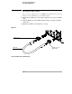

Setting Up the Oscilloscope
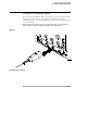
Digital probe lead set
1-23
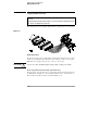
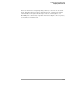
Figure 1-12
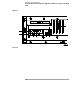
Probe Tip Isolation Network
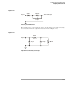
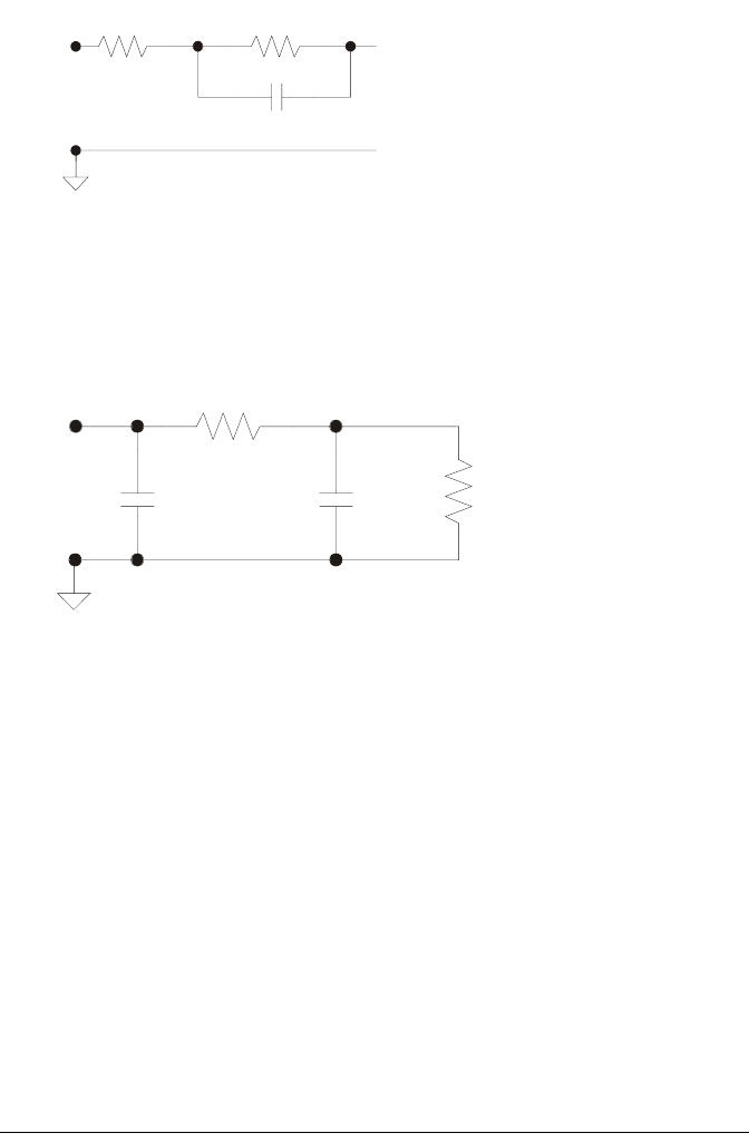
The loading effect of the probe tip on the circuit under test is represented by
the circuit shown in the equivalent load schematic in Figure 1-13.
Figure 1-13
Equivalent Load including oscilloscope
250
Ω
Signal
90.9 k
Ω
8.2 pF
To Oscilloscope
370
Ω
7.4 pF1.5 pF
100 k
Ω
Signal