
User`s guide

Setting Up the Oscilloscope
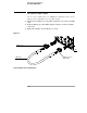
Digital probe lead set
1-22
Digital probe lead set
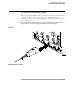
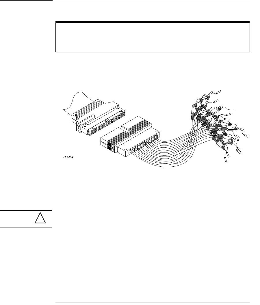
The flying lead set has 16 digital channels with a ground lead for each channel.
Figure 1-11
Digital Flying Lead Set
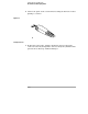
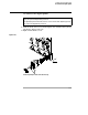
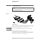
If a 0.63 mm square pin or a 0.66 diameter round pin is installed on the circuit
under test, the signal and ground leads can be directly connect to these pins.
Otherwise, the IC clips can be used to connect to the circuit.
CAUTION Do not exceed the maximum input voltage rating of ±40 V peak, CAT I.
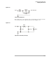
Probe tip isolation network and equivalent load
The probe tips of the probe lead set contain an isolation network which serves
to minimize the loading effect of the digital channels on the circuit under test.
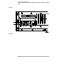
The isolation network schematic is shown in Figure 1-12.
The MSO (Mixed Signal) oscilloscopes have tightly integrated16 digital timing
channels.
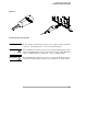
The digital flying lead marked clk (clock) is unused. All the other digital flying leads
are used for the digital timing channels.
!