
Specifications


Table Of Contents
- General Information
- Preparing for Use
- To inspect package contents
- To connect power
- To connect the mouse, keyboard, LAN, printer, and GPIB cable
- To connect the standard 10073C probes
- To connect optional InfiniiMax oscilloscope probes
- To connect the digital probe
- Digital probe lead set
- To tilt the oscilloscope upward for easier viewing
- To turn on the oscilloscope
- To turn off the oscilloscope
- To verify basic oscilloscope operation
- Installing application programs on Infiniium
- Changing Windows System Settings
- To clean the oscilloscope
- Testing Performance
- Calibrating and Adjusting
- Troubleshooting
- To install the fan safety shield
- To troubleshoot the oscilloscope
- Primary Trouble Isolation
- No Display Trouble Isolation
- To check the backlight inverter voltages
- To check the display board video signals
- Power Supply Trouble Isolation
- To check probe power outputs
- To Check the keyboard
- To check the LEDs
- To check the motherboard, CPU, and RAM
- To setup the BIOS
- To troubleshoot the acquisition system
- Software Revisions
- Replacing Assemblies
- To return the oscilloscope to Agilent Technologies for service
- To remove and replace the top cover
- To remove and replace the bottom sleeve
- To disconnect and connect Mylar flex cables
- To remove and replace the CD-ROM drive
- To remove and replace the AutoProbe assembly
- To remove and replace the internal digital input cable (MSO models only)
- To remove and replace the backlight inverter board
- To remove and replace the front panel assembly
- To remove and replace the keyboard, touch screen, and flat-panel display assemblies
- To remove and replace the acquisition board assembly
- To remove and replace the PCI bridge board
- To remove and replace the display board
- To remove and replace the hard disk drive
- To remove and replace the motherboard
- To replace the Intel motherboard with the ADLINK motherboard
- To remove and replace the power supply
- To remove and replace the fan controller board
- To remove and replace a fan
- To remove and replace the probe power and control assembly
- Replaceable Parts
- Theory of Operation
- Index
Chapter 5: Troubleshooting
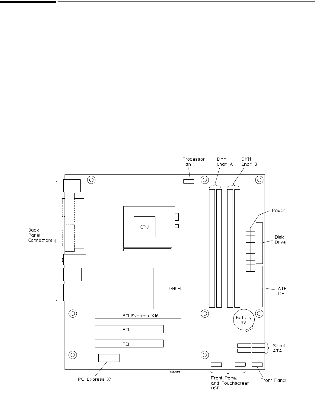
To check the motherboard, CPU, and RAM
88
To check the motherboard, CPU, and RAM
This procedure verifies that the PC system board and the associated CPU and RAM are
functioning. It assumes that the power supply, display board (when present), and an external
monitor are functioning correctly.
1
Connect an external keyboard to the keyboard port.
2 Connect an external XGA monitor to the video output connector on the rear panel.
3 Hold down the Tab key on the external keyboard, then press the power button on the
oscilloscope.
4 Verify that a message showing the Main Processor type, memory, CPU Brand, IDE
Drives, etc. momentarily appears on the monitor. The message will only appear
momentarily, then it will disappear.
5 If the message is displayed, you can assume that the PC system board, CPU, and RAM
are functioning correctly.
If you need to run setup, press DEL. Otherwise, turn off the power and proceed with
troubleshooting.
Figure 5-9
Intel D915GUX Motherboard