
Specifications


Table Of Contents
- General Information
- Preparing for Use
- To inspect package contents
- To connect power
- To connect the mouse, keyboard, LAN, printer, and GPIB cable
- To connect the standard 10073C probes
- To connect optional InfiniiMax oscilloscope probes
- To connect the digital probe
- Digital probe lead set
- To tilt the oscilloscope upward for easier viewing
- To turn on the oscilloscope
- To turn off the oscilloscope
- To verify basic oscilloscope operation
- Installing application programs on Infiniium
- Changing Windows System Settings
- To clean the oscilloscope
- Testing Performance
- Calibrating and Adjusting
- Troubleshooting
- To install the fan safety shield
- To troubleshoot the oscilloscope
- Primary Trouble Isolation
- No Display Trouble Isolation
- To check the backlight inverter voltages
- To check the display board video signals
- Power Supply Trouble Isolation
- To check probe power outputs
- To Check the keyboard
- To check the LEDs
- To check the motherboard, CPU, and RAM
- To setup the BIOS
- To troubleshoot the acquisition system
- Software Revisions
- Replacing Assemblies
- To return the oscilloscope to Agilent Technologies for service
- To remove and replace the top cover
- To remove and replace the bottom sleeve
- To disconnect and connect Mylar flex cables
- To remove and replace the CD-ROM drive
- To remove and replace the AutoProbe assembly
- To remove and replace the internal digital input cable (MSO models only)
- To remove and replace the backlight inverter board
- To remove and replace the front panel assembly
- To remove and replace the keyboard, touch screen, and flat-panel display assemblies
- To remove and replace the acquisition board assembly
- To remove and replace the PCI bridge board
- To remove and replace the display board
- To remove and replace the hard disk drive
- To remove and replace the motherboard
- To replace the Intel motherboard with the ADLINK motherboard
- To remove and replace the power supply
- To remove and replace the fan controller board
- To remove and replace a fan
- To remove and replace the probe power and control assembly
- Replaceable Parts
- Theory of Operation
- Index
Chapter 5: Troubleshooting
Power Supply Trouble Isolation
83
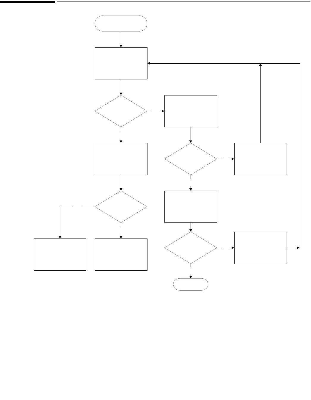
Power Supply Trouble Isolation
Power Supply Trouble Isolation Flowchart
These trouble isolation instructions help isolate the problem to the assembly level when the
power supply is not operating. Because of advanced power supply protection features, the
problem may not be with the supply itself, and therefore you will need to work through the
procedure systematically to determine the source of the fault.
A
Check the power supply voltages.
The power supply voltages are checked on the acquisition board, A13. See See Figure 5-7 for the
location of these test points. Table 5-8 shows the allowable range of power supply voltages.
Power Supply
Trouble Isolation
Check Power Supply
Voltages
Voltages OK?
Check for display on
screen
Display on
screen?
Power supply OK, go
to no-display trouble
isolation chart
Check power supply
resistances
Resistance OK?
Power-up OK?
Replace shorted
assembly
Replace Power
Supply
Yes
No
Power supply and
display OK, go to
primary trouble
isolation chart
Yes
No
No
No
A
B
C
D
E
Yes
Replace Fan Control
Board
Done
Yes