
Specifications


Table Of Contents
- General Information
- Preparing for Use
- To inspect package contents
- To connect power
- To connect the mouse, keyboard, LAN, printer, and GPIB cable
- To connect the standard 10073C probes
- To connect optional InfiniiMax oscilloscope probes
- To connect the digital probe
- Digital probe lead set
- To tilt the oscilloscope upward for easier viewing
- To turn on the oscilloscope
- To turn off the oscilloscope
- To verify basic oscilloscope operation
- Installing application programs on Infiniium
- Changing Windows System Settings
- To clean the oscilloscope
- Testing Performance
- Calibrating and Adjusting
- Troubleshooting
- To install the fan safety shield
- To troubleshoot the oscilloscope
- Primary Trouble Isolation
- No Display Trouble Isolation
- To check the backlight inverter voltages
- To check the display board video signals
- Power Supply Trouble Isolation
- To check probe power outputs
- To Check the keyboard
- To check the LEDs
- To check the motherboard, CPU, and RAM
- To setup the BIOS
- To troubleshoot the acquisition system
- Software Revisions
- Replacing Assemblies
- To return the oscilloscope to Agilent Technologies for service
- To remove and replace the top cover
- To remove and replace the bottom sleeve
- To disconnect and connect Mylar flex cables
- To remove and replace the CD-ROM drive
- To remove and replace the AutoProbe assembly
- To remove and replace the internal digital input cable (MSO models only)
- To remove and replace the backlight inverter board
- To remove and replace the front panel assembly
- To remove and replace the keyboard, touch screen, and flat-panel display assemblies
- To remove and replace the acquisition board assembly
- To remove and replace the PCI bridge board
- To remove and replace the display board
- To remove and replace the hard disk drive
- To remove and replace the motherboard
- To replace the Intel motherboard with the ADLINK motherboard
- To remove and replace the power supply
- To remove and replace the fan controller board
- To remove and replace a fan
- To remove and replace the probe power and control assembly
- Replaceable Parts
- Theory of Operation
- Index
Chapter 5: Troubleshooting
Primary Trouble Isolation
77
C
Run oscilloscope self-tests.
1 Select Self Test from the Utilities menu.
2 Select oscilloscope Self Tests from the Self Test drop down list box.
3 Select the Start Test button and follow the instructions on the screen.
If any of the Self Tests fail, go to the Acquisition Trouble Isolation troubleshooting flowchart later
in this chapter for further troubleshooting. Otherwise, go to step D.
D
Check the front panel response by running the knob, key, and LED self tests.
Use this procedure to verify correct keyboard operation.
1 Select Self Test from the Utilities menu.
2 Select Knob and Key from the Self Test drop down list box, then select Start.
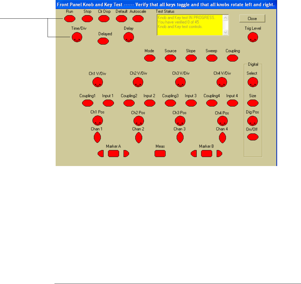
A new window appears with a symbolic representation of the keyboard. See See Figure 5-3.
Figure 5-3
Knob and Key Self Test Screen
3 Push each key on the keyboard until you have pushed all keys.
When you push a key, the corresponding key symbol on the display should change from red to
green.
4 Turn each knob in both directions until you have turned all knobs.
When you turn a knob in one direction, the corresponding knob symbol on the display should
change from red to yellow. When you then turn the knob in the other direction, the knob symbol
should change from yellow to green.
5
When you are finished, select Close.
If any of the knobs or keys do not work, see “To Check the keyboard” on page 86.
When you push a key
or turn a knob in both
directions, the
corresponding symbol
on this screen turns
green.