
Specifications


Table Of Contents
- General Information
- Preparing for Use
- To inspect package contents
- To connect power
- To connect the mouse, keyboard, LAN, printer, and GPIB cable
- To connect the standard 10073C probes
- To connect optional InfiniiMax oscilloscope probes
- To connect the digital probe
- Digital probe lead set
- To tilt the oscilloscope upward for easier viewing
- To turn on the oscilloscope
- To turn off the oscilloscope
- To verify basic oscilloscope operation
- Installing application programs on Infiniium
- Changing Windows System Settings
- To clean the oscilloscope
- Testing Performance
- Calibrating and Adjusting
- Troubleshooting
- To install the fan safety shield
- To troubleshoot the oscilloscope
- Primary Trouble Isolation
- No Display Trouble Isolation
- To check the backlight inverter voltages
- To check the display board video signals
- Power Supply Trouble Isolation
- To check probe power outputs
- To Check the keyboard
- To check the LEDs
- To check the motherboard, CPU, and RAM
- To setup the BIOS
- To troubleshoot the acquisition system
- Software Revisions
- Replacing Assemblies
- To return the oscilloscope to Agilent Technologies for service
- To remove and replace the top cover
- To remove and replace the bottom sleeve
- To disconnect and connect Mylar flex cables
- To remove and replace the CD-ROM drive
- To remove and replace the AutoProbe assembly
- To remove and replace the internal digital input cable (MSO models only)
- To remove and replace the backlight inverter board
- To remove and replace the front panel assembly
- To remove and replace the keyboard, touch screen, and flat-panel display assemblies
- To remove and replace the acquisition board assembly
- To remove and replace the PCI bridge board
- To remove and replace the display board
- To remove and replace the hard disk drive
- To remove and replace the motherboard
- To replace the Intel motherboard with the ADLINK motherboard
- To remove and replace the power supply
- To remove and replace the fan controller board
- To remove and replace a fan
- To remove and replace the probe power and control assembly
- Replaceable Parts
- Theory of Operation
- Index
Chapter 3: Testing Performance
To test delta time measurement accuracy
62
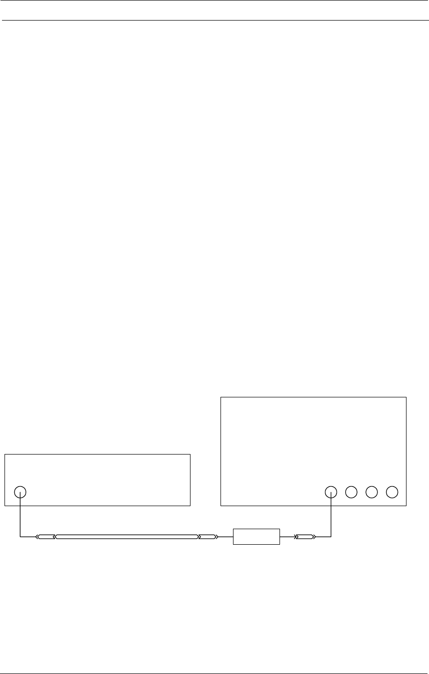
Equipment Required
Connections
Equipment Critical Specifications Recommended Model/Part
Sine wave source Output Frequency: 50 MHz to 7 GHz
Output Amplitude: -10 dBm to 10 dBm
Absolute Frequency Error: < +-1 ppm
Period Jitter: < 0.1 times the published typical
period jitter of the oscilloscope under test
when used with the specified band-pass
filter.
Agilent E8257 PSG
Microwave cable
assembly
50 ohm characteristic impedance (no
substitute)
3.5 mm (m) connectors
Max Frequency: >= 18 GHz
Agilent 8120-4948
Adapters, assorted 3.5 mm (f) to Precision BNC (m)
3.5 mm (f) to 3.5 mm (f)
SMA (f) to BNC (m)
Agilent 54855-67604
Agilent 83059B
Amphenol 901-165
500 MHz Band-pass
Filter
(for 8104 only)
Center Freq: 500 MHz
Pass 3dB BW: 50 MHz
Insertion Loss.: 2.1 dB
Attn @ 400 MHz: 35 dB
Attn @ 600 MHz: 35 dB
K&L Microwave
4LB40-500/T50-O/OP
300 MHz Band-pass
Filter
(for 8064 only)
Center Freq: 300 MHz
Pass 3dB BW: 20 MHz
Insertion Loss.: 3.3 dB
Attn @ 260 MHz: 36 dB
Attn @ 340 MHz: 36 dB
K&L Microwave
4LB40-300/T20-O/OP
Oscilloscope
Sine Wave Source
Filter
Adapter
(optional)
Cable
Adapter
(optional)
Adapter
(optional)