
Specifications


Table Of Contents
- General Information
- Preparing for Use
- To inspect package contents
- To connect power
- To connect the mouse, keyboard, LAN, printer, and GPIB cable
- To connect the standard 10073C probes
- To connect optional InfiniiMax oscilloscope probes
- To connect the digital probe
- Digital probe lead set
- To tilt the oscilloscope upward for easier viewing
- To turn on the oscilloscope
- To turn off the oscilloscope
- To verify basic oscilloscope operation
- Installing application programs on Infiniium
- Changing Windows System Settings
- To clean the oscilloscope
- Testing Performance
- Calibrating and Adjusting
- Troubleshooting
- To install the fan safety shield
- To troubleshoot the oscilloscope
- Primary Trouble Isolation
- No Display Trouble Isolation
- To check the backlight inverter voltages
- To check the display board video signals
- Power Supply Trouble Isolation
- To check probe power outputs
- To Check the keyboard
- To check the LEDs
- To check the motherboard, CPU, and RAM
- To setup the BIOS
- To troubleshoot the acquisition system
- Software Revisions
- Replacing Assemblies
- To return the oscilloscope to Agilent Technologies for service
- To remove and replace the top cover
- To remove and replace the bottom sleeve
- To disconnect and connect Mylar flex cables
- To remove and replace the CD-ROM drive
- To remove and replace the AutoProbe assembly
- To remove and replace the internal digital input cable (MSO models only)
- To remove and replace the backlight inverter board
- To remove and replace the front panel assembly
- To remove and replace the keyboard, touch screen, and flat-panel display assemblies
- To remove and replace the acquisition board assembly
- To remove and replace the PCI bridge board
- To remove and replace the display board
- To remove and replace the hard disk drive
- To remove and replace the motherboard
- To replace the Intel motherboard with the ADLINK motherboard
- To remove and replace the power supply
- To remove and replace the fan controller board
- To remove and replace a fan
- To remove and replace the probe power and control assembly
- Replaceable Parts
- Theory of Operation
- Index
Chapter 3: Testing Performance
To test time scale accuracy
60
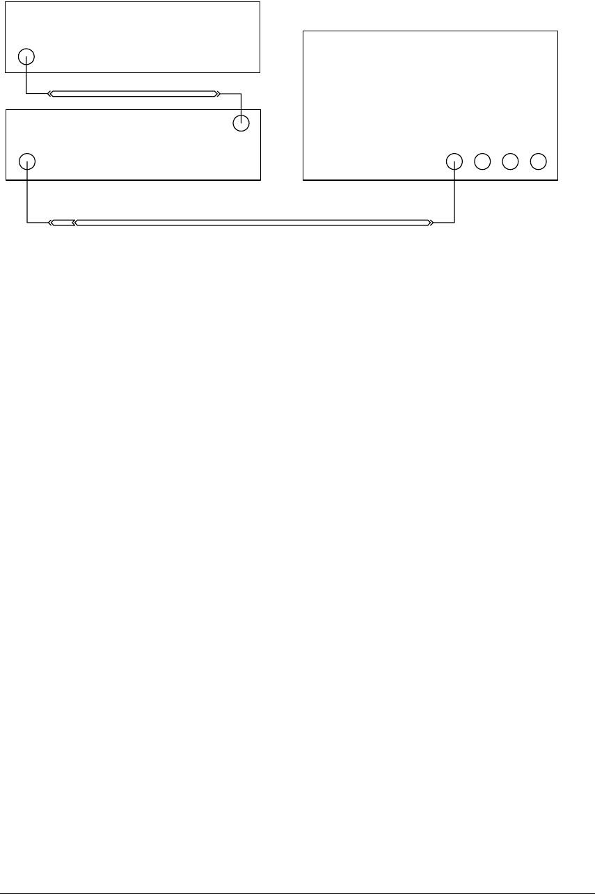
Connections
Procedure
1
Configure the sine wave source to output a 0 dBm (600 mVpp) sine wave into 50 ohms
with a frequency of 10.0002000 MHz.
2 Adjust source amplitude such that displayed sine wave is 600 mVpp.
3 Press the Default Setup key on the oscilloscope.
4 Set channel 1's vertical scale to 100 mV/div.
5 Set the oscilloscope sample rate to 100 kSa/s. (The resulting measurement will be
aliased.)
6 Set the scope's horizontal scale to 10 ms/div.
7 Set the scope's input impedance to 50 ohms.
8 Set the measurement thresholds for all waveforms to a fixed voltage level of 0 V and
±20 mV hysteresis.
9 Enable a frequency measurement on channel 1.
10 On the oscilloscope, press Stop.
11 Press Clear Display.
12 Press Run, wait until 10 acquisitions have accumulated, and then press Stop.
13 Convert the average frequency value to time scale error by subtracting 200 Hz and
dividing by 10 Hz/ppm.
14 Record the time scale error value as well as the time (in years) since the oscilloscope
was manufactured .
15 Compare the measured TSA value to the TSA test limits in the Performance Test Record
and record the results.
Oscilloscope
Sine Wave Source
Adapter
(optional)
Cable
Frequency Reference
Cable
Ref In