
Specifications


Table Of Contents
- General Information
- Preparing for Use
- To inspect package contents
- To connect power
- To connect the mouse, keyboard, LAN, printer, and GPIB cable
- To connect the standard 10073C probes
- To connect optional InfiniiMax oscilloscope probes
- To connect the digital probe
- Digital probe lead set
- To tilt the oscilloscope upward for easier viewing
- To turn on the oscilloscope
- To turn off the oscilloscope
- To verify basic oscilloscope operation
- Installing application programs on Infiniium
- Changing Windows System Settings
- To clean the oscilloscope
- Testing Performance
- Calibrating and Adjusting
- Troubleshooting
- To install the fan safety shield
- To troubleshoot the oscilloscope
- Primary Trouble Isolation
- No Display Trouble Isolation
- To check the backlight inverter voltages
- To check the display board video signals
- Power Supply Trouble Isolation
- To check probe power outputs
- To Check the keyboard
- To check the LEDs
- To check the motherboard, CPU, and RAM
- To setup the BIOS
- To troubleshoot the acquisition system
- Software Revisions
- Replacing Assemblies
- To return the oscilloscope to Agilent Technologies for service
- To remove and replace the top cover
- To remove and replace the bottom sleeve
- To disconnect and connect Mylar flex cables
- To remove and replace the CD-ROM drive
- To remove and replace the AutoProbe assembly
- To remove and replace the internal digital input cable (MSO models only)
- To remove and replace the backlight inverter board
- To remove and replace the front panel assembly
- To remove and replace the keyboard, touch screen, and flat-panel display assemblies
- To remove and replace the acquisition board assembly
- To remove and replace the PCI bridge board
- To remove and replace the display board
- To remove and replace the hard disk drive
- To remove and replace the motherboard
- To replace the Intel motherboard with the ADLINK motherboard
- To remove and replace the power supply
- To remove and replace the fan controller board
- To remove and replace a fan
- To remove and replace the probe power and control assembly
- Replaceable Parts
- Theory of Operation
- Index
Chapter 3: Testing Performance
To verify threshold accuracy
52
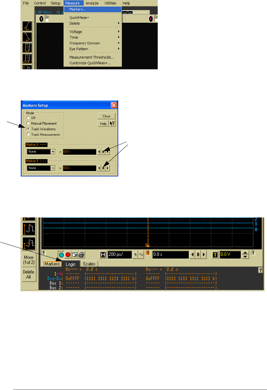
f Select Measure from the menu bar and then select Markers...
g Set the mode to Track Waveforms.
h Set the position of both markers to center screen by selecting the 0 buttons for each
marker.
i Close the Marker Setup window.
j Display the states of the digital bits at the markers in both hexadecimal and binary forms
by selecting the Logic tab in the marker display area at the bottom of the LCD display.
Note: The data in the left column shows the states of the digital inputs at the Cursor A
position and the data in the right column shows the states of the digital inputs at the
Cursor B position.
k Set the oscilloscope digital threshold to the value being tested (e.g. +5V, 0V or -5V) as
follows:
From the menu bar, select Setup, then select Digital..., then select the Threshold tab.
Make the following settings for both pods:
Set the Logic Family to User Defined.
Set the Threshold for both pods to the value being tested. Start with the first value of
Select here
Select here
Select the
logic tab