
Specifications


Table Of Contents
- General Information
- Preparing for Use
- To inspect package contents
- To connect power
- To connect the mouse, keyboard, LAN, printer, and GPIB cable
- To connect the standard 10073C probes
- To connect optional InfiniiMax oscilloscope probes
- To connect the digital probe
- Digital probe lead set
- To tilt the oscilloscope upward for easier viewing
- To turn on the oscilloscope
- To turn off the oscilloscope
- To verify basic oscilloscope operation
- Installing application programs on Infiniium
- Changing Windows System Settings
- To clean the oscilloscope
- Testing Performance
- Calibrating and Adjusting
- Troubleshooting
- To install the fan safety shield
- To troubleshoot the oscilloscope
- Primary Trouble Isolation
- No Display Trouble Isolation
- To check the backlight inverter voltages
- To check the display board video signals
- Power Supply Trouble Isolation
- To check probe power outputs
- To Check the keyboard
- To check the LEDs
- To check the motherboard, CPU, and RAM
- To setup the BIOS
- To troubleshoot the acquisition system
- Software Revisions
- Replacing Assemblies
- To return the oscilloscope to Agilent Technologies for service
- To remove and replace the top cover
- To remove and replace the bottom sleeve
- To disconnect and connect Mylar flex cables
- To remove and replace the CD-ROM drive
- To remove and replace the AutoProbe assembly
- To remove and replace the internal digital input cable (MSO models only)
- To remove and replace the backlight inverter board
- To remove and replace the front panel assembly
- To remove and replace the keyboard, touch screen, and flat-panel display assemblies
- To remove and replace the acquisition board assembly
- To remove and replace the PCI bridge board
- To remove and replace the display board
- To remove and replace the hard disk drive
- To remove and replace the motherboard
- To replace the Intel motherboard with the ADLINK motherboard
- To remove and replace the power supply
- To remove and replace the fan controller board
- To remove and replace a fan
- To remove and replace the probe power and control assembly
- Replaceable Parts
- Theory of Operation
- Index
Chapter 3: Testing Performance
To verify threshold accuracy
51
3
Power on the instruments and wait at least 30 minutes for the system to warm up before
beginning this test.
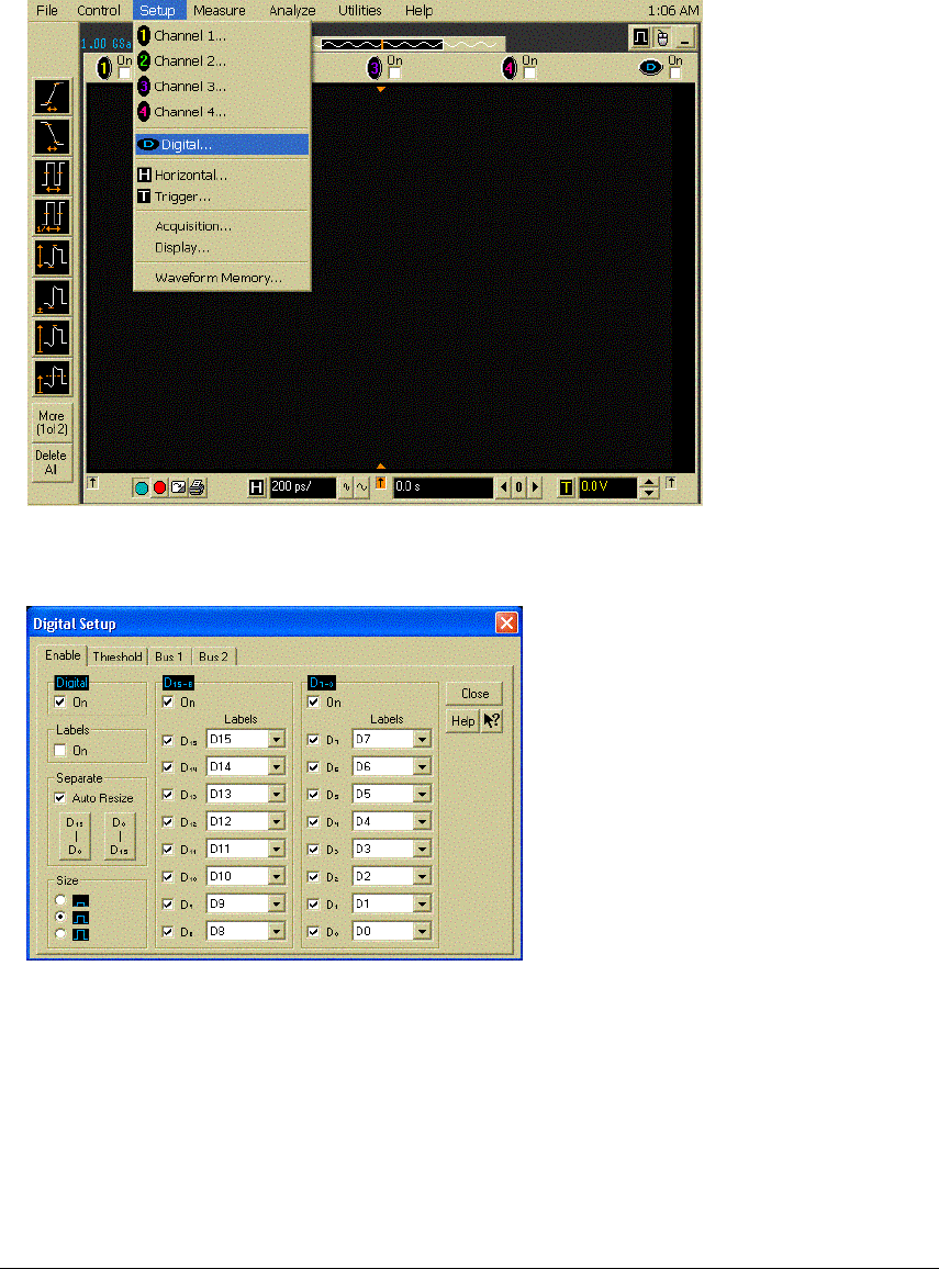
4 Prepare the oscilloscope for test.
a Press the Default Setup button on the front panel.
b If the digital channels are not already displayed, press the D15-0 button on the lower
right corner of the front panel.
c From the menu bar, select Setup and then select Digital...
d Ensure that Enable tab is selected. Ensure that the On checkboxes for all 16 bits have
check marks.
e Close the Digital Setup window.