
Specifications


Table Of Contents
- General Information
- Preparing for Use
- To inspect package contents
- To connect power
- To connect the mouse, keyboard, LAN, printer, and GPIB cable
- To connect the standard 10073C probes
- To connect optional InfiniiMax oscilloscope probes
- To connect the digital probe
- Digital probe lead set
- To tilt the oscilloscope upward for easier viewing
- To turn on the oscilloscope
- To turn off the oscilloscope
- To verify basic oscilloscope operation
- Installing application programs on Infiniium
- Changing Windows System Settings
- To clean the oscilloscope
- Testing Performance
- Calibrating and Adjusting
- Troubleshooting
- To install the fan safety shield
- To troubleshoot the oscilloscope
- Primary Trouble Isolation
- No Display Trouble Isolation
- To check the backlight inverter voltages
- To check the display board video signals
- Power Supply Trouble Isolation
- To check probe power outputs
- To Check the keyboard
- To check the LEDs
- To check the motherboard, CPU, and RAM
- To setup the BIOS
- To troubleshoot the acquisition system
- Software Revisions
- Replacing Assemblies
- To return the oscilloscope to Agilent Technologies for service
- To remove and replace the top cover
- To remove and replace the bottom sleeve
- To disconnect and connect Mylar flex cables
- To remove and replace the CD-ROM drive
- To remove and replace the AutoProbe assembly
- To remove and replace the internal digital input cable (MSO models only)
- To remove and replace the backlight inverter board
- To remove and replace the front panel assembly
- To remove and replace the keyboard, touch screen, and flat-panel display assemblies
- To remove and replace the acquisition board assembly
- To remove and replace the PCI bridge board
- To remove and replace the display board
- To remove and replace the hard disk drive
- To remove and replace the motherboard
- To replace the Intel motherboard with the ADLINK motherboard
- To remove and replace the power supply
- To remove and replace the fan controller board
- To remove and replace a fan
- To remove and replace the probe power and control assembly
- Replaceable Parts
- Theory of Operation
- Index
Chapter 3: Testing Performance
To test single cursor voltage measurement accuracy with offset
46
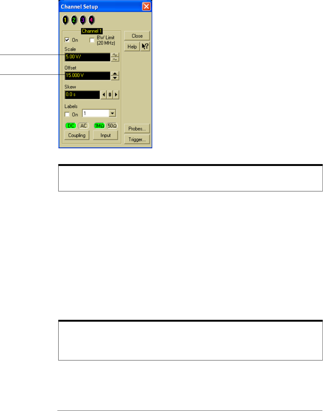
Figure 3-6
Vertical Scaling and Offset for Voltage Accuracy Measurement
11 With the supply disconnected from the channel input, note the V
avg
mean reading.
____________ V
It may take a moment for this value to settle because of averaging.
12 Set the power supply voltage from the first line of the table. Use the voltmeter to adjust
the power supply for the most accurate output.
13 Connect the power supply to the channel input and note the V
avg
reading. _________ V
Press Clear Display and wait a moment to read the value (so that averaging is complete).
14
Subtract the value in step 11 from the value in step 13. Record the difference in the
Performance Test Record.
15 On the same channel, repeat steps 10 through 14 for the rest of the rows in the table.
16 With the channel keys, set the active channel OFF and the next ON.
A channel is ON if its key is illuminated and OFF if it is not illuminated.
17
Move the BNC tee to the next channel and repeat steps 8 through 15 for that channel.
18 Repeat steps 8 through 17 for the rest of the channels.
To Set Vertical Scale and Position
You can also use the knobs to set the vertical scale and position, but it is usually easier to use the dialog
box, particularly for the fine position setting.
If the test fails
Voltage measurement errors can be caused by the need for self-calibration. Before troubleshooting the
oscilloscope, perform self-calibration. See “To run the self-calibration” in chapter 4, “Calibrating and
Adjusting.” If self-calibration fails to correct the problem, the cause may be the attenuator or main
assembly.
Set the scale from the
table
Set the offset from the
table