
Specifications


Table Of Contents
- General Information
- Preparing for Use
- To inspect package contents
- To connect power
- To connect the mouse, keyboard, LAN, printer, and GPIB cable
- To connect the standard 10073C probes
- To connect optional InfiniiMax oscilloscope probes
- To connect the digital probe
- Digital probe lead set
- To tilt the oscilloscope upward for easier viewing
- To turn on the oscilloscope
- To turn off the oscilloscope
- To verify basic oscilloscope operation
- Installing application programs on Infiniium
- Changing Windows System Settings
- To clean the oscilloscope
- Testing Performance
- Calibrating and Adjusting
- Troubleshooting
- To install the fan safety shield
- To troubleshoot the oscilloscope
- Primary Trouble Isolation
- No Display Trouble Isolation
- To check the backlight inverter voltages
- To check the display board video signals
- Power Supply Trouble Isolation
- To check probe power outputs
- To Check the keyboard
- To check the LEDs
- To check the motherboard, CPU, and RAM
- To setup the BIOS
- To troubleshoot the acquisition system
- Software Revisions
- Replacing Assemblies
- To return the oscilloscope to Agilent Technologies for service
- To remove and replace the top cover
- To remove and replace the bottom sleeve
- To disconnect and connect Mylar flex cables
- To remove and replace the CD-ROM drive
- To remove and replace the AutoProbe assembly
- To remove and replace the internal digital input cable (MSO models only)
- To remove and replace the backlight inverter board
- To remove and replace the front panel assembly
- To remove and replace the keyboard, touch screen, and flat-panel display assemblies
- To remove and replace the acquisition board assembly
- To remove and replace the PCI bridge board
- To remove and replace the display board
- To remove and replace the hard disk drive
- To remove and replace the motherboard
- To replace the Intel motherboard with the ADLINK motherboard
- To remove and replace the power supply
- To remove and replace the fan controller board
- To remove and replace a fan
- To remove and replace the probe power and control assembly
- Replaceable Parts
- Theory of Operation
- Index
Chapter 3: Testing Performance
To test single cursor voltage measurement accuracy with offset
45
8
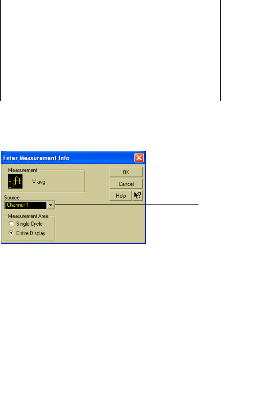
Select Vavg from the Voltage submenu of the Measure menu. Ensure that Channel 1 is
selected in the "Enter Measurement Info" dialog and select OK.
See Figure 3-5.
Figure 3-5
Source Selection for Vavg Measurement
9 Select Channel 1 from the Setup menu.
10 Set the sensitivity for Channel 1 to the volts/div value from the first row of the table in
step 7. Set the Offset control to the offset value from the first row of the same table.
Select Close.
See Figure 3-6.
Sensitivity Channel Vin Tolerance Limits
(Volts/div) Offset (Supply) Minimum Maximum
5 V 17.5 V 35 V +/- 1.52 V 33.48 V 36.52 V
2 V 7 V 14 V +/- 609 mV 13.39 V 14.61 V
1.25 V 4.375 V 8.75 V +/- 576 mV 8.17 V 9.33 V
500 mV 1.75 V 3.5 V +/- 153 mV 3.35 V 3.65 V
250 mV 875 mV 1.75 V +/- 142 mV 1.61 V 1.89 V
100 mV 350 mV 700 mV +/- 31.4 mV 669 mV 731 mV
50 mV 175 mV 350 mV +/- 16.2 mV 334 mV 366 mV
20 mV 70 mV 140 mV +/- 7.08 mV 133 mV 147 mV
10 mV 35 mV 70 mV +/- 4.04 mV 66 mV 74.0 mV
5 mV 17.5 mV 35 mV +/- 2.52 mV 32.5 mV 37.5 mV
Select Channel 1 as the
source for the Vavg
measurement