
Specifications


Table Of Contents
- General Information
- Preparing for Use
- To inspect package contents
- To connect power
- To connect the mouse, keyboard, LAN, printer, and GPIB cable
- To connect the standard 10073C probes
- To connect optional InfiniiMax oscilloscope probes
- To connect the digital probe
- Digital probe lead set
- To tilt the oscilloscope upward for easier viewing
- To turn on the oscilloscope
- To turn off the oscilloscope
- To verify basic oscilloscope operation
- Installing application programs on Infiniium
- Changing Windows System Settings
- To clean the oscilloscope
- Testing Performance
- Calibrating and Adjusting
- Troubleshooting
- To install the fan safety shield
- To troubleshoot the oscilloscope
- Primary Trouble Isolation
- No Display Trouble Isolation
- To check the backlight inverter voltages
- To check the display board video signals
- Power Supply Trouble Isolation
- To check probe power outputs
- To Check the keyboard
- To check the LEDs
- To check the motherboard, CPU, and RAM
- To setup the BIOS
- To troubleshoot the acquisition system
- Software Revisions
- Replacing Assemblies
- To return the oscilloscope to Agilent Technologies for service
- To remove and replace the top cover
- To remove and replace the bottom sleeve
- To disconnect and connect Mylar flex cables
- To remove and replace the CD-ROM drive
- To remove and replace the AutoProbe assembly
- To remove and replace the internal digital input cable (MSO models only)
- To remove and replace the backlight inverter board
- To remove and replace the front panel assembly
- To remove and replace the keyboard, touch screen, and flat-panel display assemblies
- To remove and replace the acquisition board assembly
- To remove and replace the PCI bridge board
- To remove and replace the display board
- To remove and replace the hard disk drive
- To remove and replace the motherboard
- To replace the Intel motherboard with the ADLINK motherboard
- To remove and replace the power supply
- To remove and replace the fan controller board
- To remove and replace a fan
- To remove and replace the probe power and control assembly
- Replaceable Parts
- Theory of Operation
- Index
Chapter 3: Testing Performance
To test input resistance
42
To test input resistance
This test checks the input resistance of the vertical inputs. A four-wire measurement is used to
accurately measure the 50 Ω and 1 MΩ inputs.
Specification: 1 MΩ ±1% and 50 Ω ±1.5%
Equipment Required
Procedure
1
Set up the multimeter to make a four-wire resistance measurement.
2 Assemble the test cables.
a Use the two BNC-to-banana adapters to connect one end of each BNC cable to the four-
wire resistance connections on the multimeter.
b Connect the free ends of the cables to the BNC tee.
See Figure 3-2.
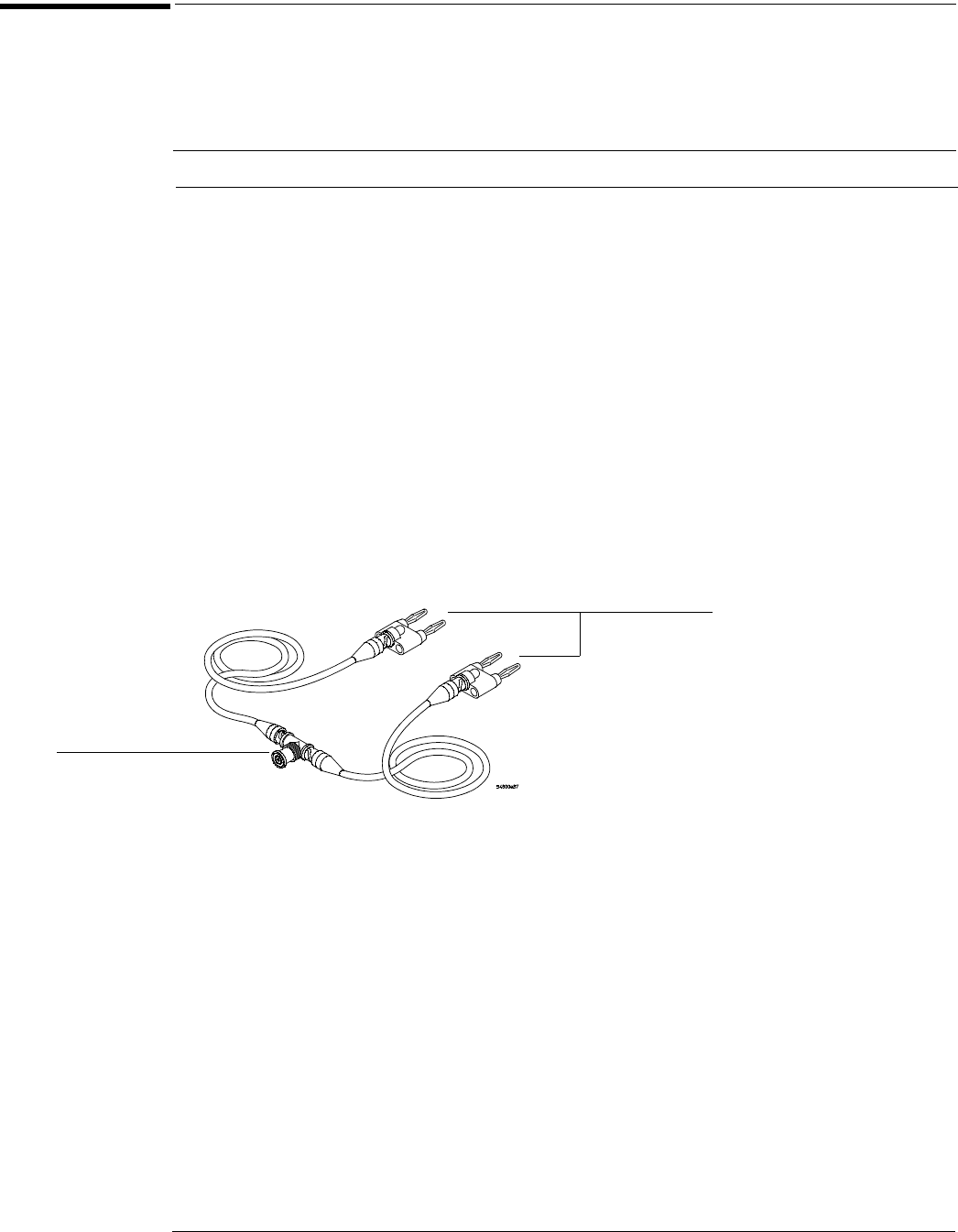
Figure 3-2
Input Resistance Equipment Setup
3 Connect the male end of the BNC tee to the channel 1 input of the oscilloscope.
4 Press Default Setup to set the oscilloscope to default conditions.
5 Press the Input key for Channel 1 to select 1 MΩ, then 50 Ω, and verify resistance
readings of 1 MΩ ±10 kΩ and 50 Ω ±0.75 Ω respectively.
6 Record the readings in the Performance Test Record.
7 Repeat steps 3 through 6 on the remaining channels, and on the external trigger of the
oscilloscope.
Equipment Critical Specifications Recommended Model/Part
Digital Multimeter Measure resistance (4-wire) at better than
±0.1% accuracy
Agilent 34401A
Cables (2) BNC Agilent 10503A
Adapter BNC Tee (m)(f)(f) Agilent 1250-0781
Adapters (2) BNC (f) to dual banana (m) Agilent 1251-2277
To ohmmeter
4-wire inputs
To oscilloscope
channel input