
Specifications


Table Of Contents
- General Information
- Preparing for Use
- To inspect package contents
- To connect power
- To connect the mouse, keyboard, LAN, printer, and GPIB cable
- To connect the standard 10073C probes
- To connect optional InfiniiMax oscilloscope probes
- To connect the digital probe
- Digital probe lead set
- To tilt the oscilloscope upward for easier viewing
- To turn on the oscilloscope
- To turn off the oscilloscope
- To verify basic oscilloscope operation
- Installing application programs on Infiniium
- Changing Windows System Settings
- To clean the oscilloscope
- Testing Performance
- Calibrating and Adjusting
- Troubleshooting
- To install the fan safety shield
- To troubleshoot the oscilloscope
- Primary Trouble Isolation
- No Display Trouble Isolation
- To check the backlight inverter voltages
- To check the display board video signals
- Power Supply Trouble Isolation
- To check probe power outputs
- To Check the keyboard
- To check the LEDs
- To check the motherboard, CPU, and RAM
- To setup the BIOS
- To troubleshoot the acquisition system
- Software Revisions
- Replacing Assemblies
- To return the oscilloscope to Agilent Technologies for service
- To remove and replace the top cover
- To remove and replace the bottom sleeve
- To disconnect and connect Mylar flex cables
- To remove and replace the CD-ROM drive
- To remove and replace the AutoProbe assembly
- To remove and replace the internal digital input cable (MSO models only)
- To remove and replace the backlight inverter board
- To remove and replace the front panel assembly
- To remove and replace the keyboard, touch screen, and flat-panel display assemblies
- To remove and replace the acquisition board assembly
- To remove and replace the PCI bridge board
- To remove and replace the display board
- To remove and replace the hard disk drive
- To remove and replace the motherboard
- To replace the Intel motherboard with the ADLINK motherboard
- To remove and replace the power supply
- To remove and replace the fan controller board
- To remove and replace a fan
- To remove and replace the probe power and control assembly
- Replaceable Parts
- Theory of Operation
- Index
Chapter 3: Testing Performance
To test the DC calibrator
40
To test the DC calibrator
The Aux Out BNC on the back panel is used for self-calibration. Though calibrator accuracy is
not specified in the performance specifications, it must be within limits in order to provide
accurate self-calibration.
Test Limits: -2.4 v to +2.4 v, DC gain accuracy ±0.2%
Equipment Required
Procedure
1
Connect the multimeter to the back panel Aux Out BNC.
Use the BNC cable and the BNC to banana plug adapter.
2
Press Default Setup to set the oscilloscope to default conditions.
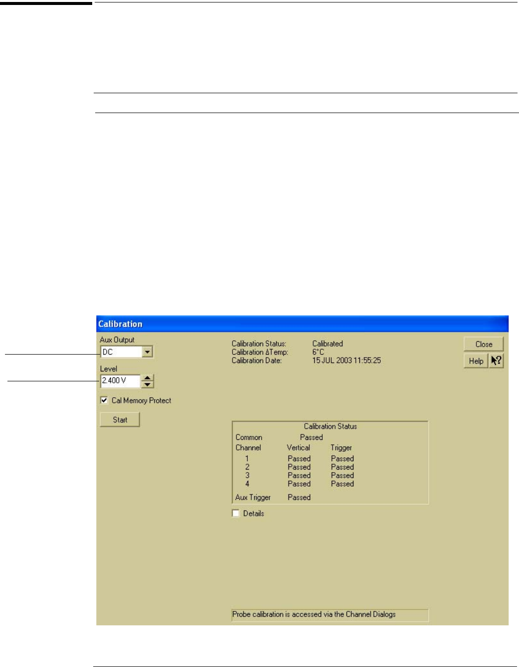
3 Select Calibration from the Utilities menu.
4 Select DC from the Aux Output drop-down list box.
See Figure 3-1.
Figure 3-1
Selecting DC in the Calibration Dialog
Equipment Critical Specifications Recommended Model/Part
Digital Multimeter 0.1 mV resolution, better than 0.1% accuracy Agilent 34401A
Cable BNC Agilent 10503A
Adapter BNC (f) to banana (m) Agilent 1251-2277
Set Aux Output to DC
Set the output voltage