
Specifications


Table Of Contents
- General Information
- Preparing for Use
- To inspect package contents
- To connect power
- To connect the mouse, keyboard, LAN, printer, and GPIB cable
- To connect the standard 10073C probes
- To connect optional InfiniiMax oscilloscope probes
- To connect the digital probe
- Digital probe lead set
- To tilt the oscilloscope upward for easier viewing
- To turn on the oscilloscope
- To turn off the oscilloscope
- To verify basic oscilloscope operation
- Installing application programs on Infiniium
- Changing Windows System Settings
- To clean the oscilloscope
- Testing Performance
- Calibrating and Adjusting
- Troubleshooting
- To install the fan safety shield
- To troubleshoot the oscilloscope
- Primary Trouble Isolation
- No Display Trouble Isolation
- To check the backlight inverter voltages
- To check the display board video signals
- Power Supply Trouble Isolation
- To check probe power outputs
- To Check the keyboard
- To check the LEDs
- To check the motherboard, CPU, and RAM
- To setup the BIOS
- To troubleshoot the acquisition system
- Software Revisions
- Replacing Assemblies
- To return the oscilloscope to Agilent Technologies for service
- To remove and replace the top cover
- To remove and replace the bottom sleeve
- To disconnect and connect Mylar flex cables
- To remove and replace the CD-ROM drive
- To remove and replace the AutoProbe assembly
- To remove and replace the internal digital input cable (MSO models only)
- To remove and replace the backlight inverter board
- To remove and replace the front panel assembly
- To remove and replace the keyboard, touch screen, and flat-panel display assemblies
- To remove and replace the acquisition board assembly
- To remove and replace the PCI bridge board
- To remove and replace the display board
- To remove and replace the hard disk drive
- To remove and replace the motherboard
- To replace the Intel motherboard with the ADLINK motherboard
- To remove and replace the power supply
- To remove and replace the fan controller board
- To remove and replace a fan
- To remove and replace the probe power and control assembly
- Replaceable Parts
- Theory of Operation
- Index
Chapter 2: Preparing for Use
Digital probe lead set
30
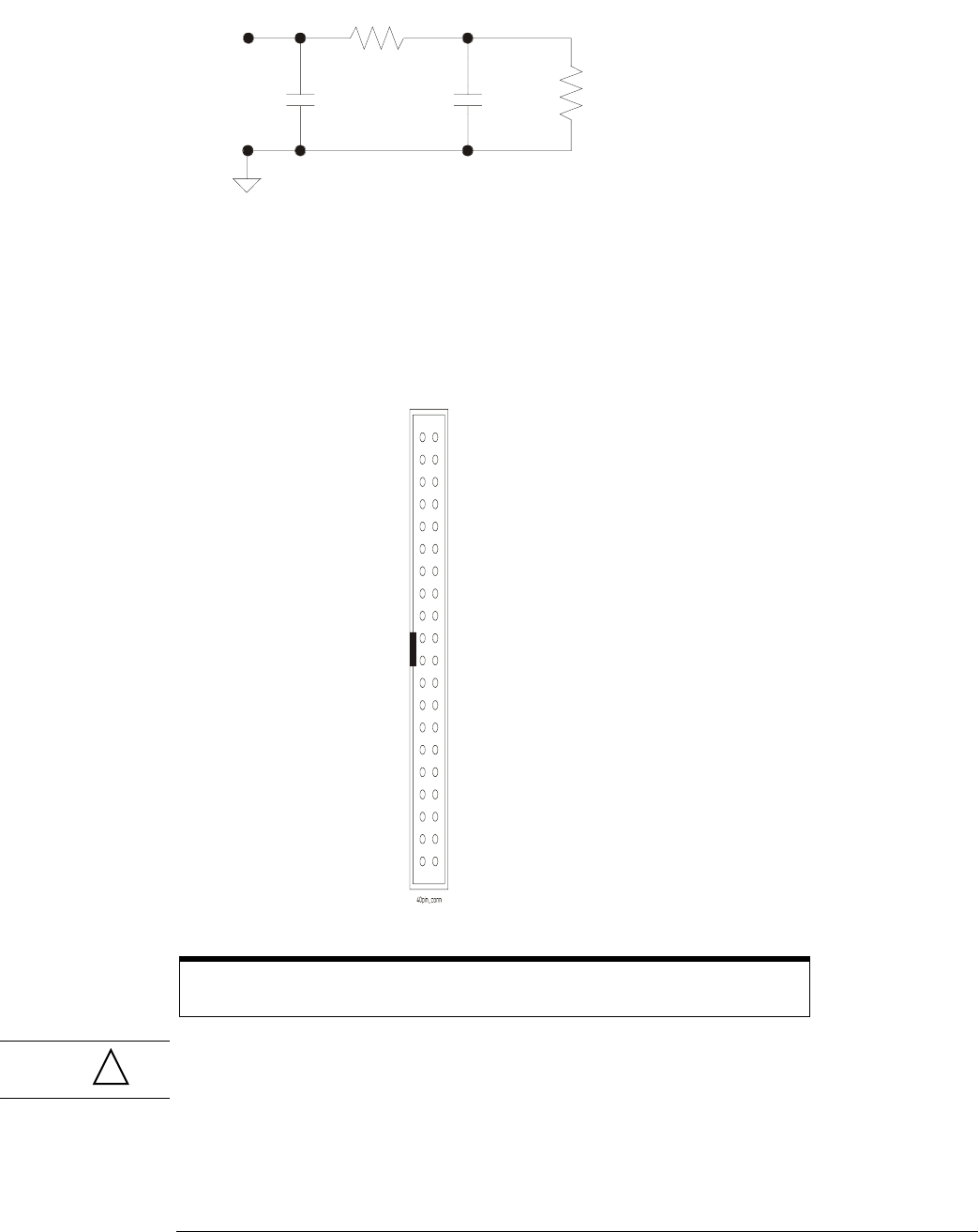
Figure 2-12
Equivalent Load including oscilloscope
Direct connection through 40-pin connector
The probe cable can also be directly plugged into various 40-pin connectors on the circuit board
under test. This requires each signal pin of the 40-pin connector to have an isolation network
(see Figure 2-11) on the circuit board. The pinout of the 40-pin connector is shown in Figure 2-13.
Figure 2-13
40-pin Connector Pinout
CAUTION Do not exceed the maximum input voltage rating of ±40 V peak, CAT I. The isolation network
(see Figure 2-11) must be used on all digital channels for this to be valid.
For more information on digital probing solutions, search for document number 5968-4632E on
the Agilent Technologies web site at www.agilent.com. This document is titled “Probing Solutions
for Logic Analysis Systems.” It appears under the heading “Data Sheets, Demonstrations &
Catalogs.”
Note: +5 V is supplied by the oscilloscope to provide power for the demo board.
DO NOT connect these pins to the circuit board under test.
370
Ω
7.4 pF1.5 pF
100 k
Ω
Signal
D0
37
D1
35
D2
33
D3
31
D4
29
D5
27
D6
25
D7
23
D8
21
D9
19
D10
17
D11
15
D12
13
D13
11
D14
9
D15
7
Do not connect
5
Unused
3
+5 V (see note)
1
+5 V (see note)
39
38
36
34
32
30
28
26
24
22
20
18
16
14
12
10
8
6
4
2
40
Power Gnd
Power Gnd
Signal Gnd
Signal Gnd
Signal Gnd
Signal Gnd
Signal Gnd
Signal Gnd
Signal Gnd
Signal Gnd
Signal Gnd
Signal Gnd
Signal Gnd
Signal Gnd
Signal Gnd
Signal Gnd
Signal Gnd
Signal Gnd
Signal Gnd
Signal Gnd
!