
Specifications


Table Of Contents
- General Information
- Preparing for Use
- To inspect package contents
- To connect power
- To connect the mouse, keyboard, LAN, printer, and GPIB cable
- To connect the standard 10073C probes
- To connect optional InfiniiMax oscilloscope probes
- To connect the digital probe
- Digital probe lead set
- To tilt the oscilloscope upward for easier viewing
- To turn on the oscilloscope
- To turn off the oscilloscope
- To verify basic oscilloscope operation
- Installing application programs on Infiniium
- Changing Windows System Settings
- To clean the oscilloscope
- Testing Performance
- Calibrating and Adjusting
- Troubleshooting
- To install the fan safety shield
- To troubleshoot the oscilloscope
- Primary Trouble Isolation
- No Display Trouble Isolation
- To check the backlight inverter voltages
- To check the display board video signals
- Power Supply Trouble Isolation
- To check probe power outputs
- To Check the keyboard
- To check the LEDs
- To check the motherboard, CPU, and RAM
- To setup the BIOS
- To troubleshoot the acquisition system
- Software Revisions
- Replacing Assemblies
- To return the oscilloscope to Agilent Technologies for service
- To remove and replace the top cover
- To remove and replace the bottom sleeve
- To disconnect and connect Mylar flex cables
- To remove and replace the CD-ROM drive
- To remove and replace the AutoProbe assembly
- To remove and replace the internal digital input cable (MSO models only)
- To remove and replace the backlight inverter board
- To remove and replace the front panel assembly
- To remove and replace the keyboard, touch screen, and flat-panel display assemblies
- To remove and replace the acquisition board assembly
- To remove and replace the PCI bridge board
- To remove and replace the display board
- To remove and replace the hard disk drive
- To remove and replace the motherboard
- To replace the Intel motherboard with the ADLINK motherboard
- To remove and replace the power supply
- To remove and replace the fan controller board
- To remove and replace a fan
- To remove and replace the probe power and control assembly
- Replaceable Parts
- Theory of Operation
- Index
Chapter 2: Preparing for Use
Digital probe lead set
29
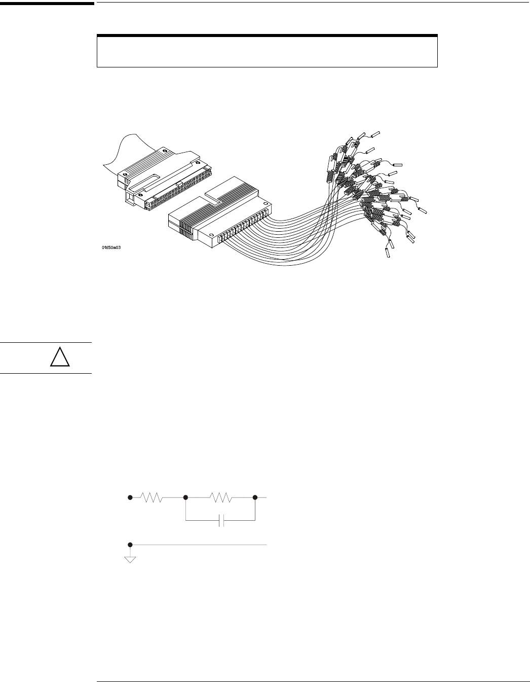
Digital probe lead set
The probe lead set has 16 digital channels with a ground lead for each channel.
Figure 2-10
Digital Probe Lead Set
If a 0.63 mm square pin or a 0.66 diameter round pin is installed on the circuit under test, the
signal and ground leads can be directly connect to these pins. Otherwise, the IC clips can be
used to connect to the circuit.
CAUTION Do not exceed the maximum input voltage rating of ±40 V peak, CAT I.
Probe tip isolation network and equivalent load
The probe tips of the probe lead set contain an isolation network which serves to minimize the
loading effect of the digital channels on the circuit under test. The isolation network schematic
is shown in Figure 2-11.
Figure 2-11
Probe Tip Isolation Network
The loading effect of the probe tip on the circuit under test is represented by the circuit shown
in the equivalent load schematic in Figure 2-12.
The digital clip lead marked clk (clock) is unused. All the other digital clip leads
are used for the digital channels.
!
250
Ω
Signal
90.9 k
Ω
8.2 pF
To Oscilloscope