
Specifications


Table Of Contents
- General Information
- Preparing for Use
- To inspect package contents
- To connect power
- To connect the mouse, keyboard, LAN, printer, and GPIB cable
- To connect the standard 10073C probes
- To connect optional InfiniiMax oscilloscope probes
- To connect the digital probe
- Digital probe lead set
- To tilt the oscilloscope upward for easier viewing
- To turn on the oscilloscope
- To turn off the oscilloscope
- To verify basic oscilloscope operation
- Installing application programs on Infiniium
- Changing Windows System Settings
- To clean the oscilloscope
- Testing Performance
- Calibrating and Adjusting
- Troubleshooting
- To install the fan safety shield
- To troubleshoot the oscilloscope
- Primary Trouble Isolation
- No Display Trouble Isolation
- To check the backlight inverter voltages
- To check the display board video signals
- Power Supply Trouble Isolation
- To check probe power outputs
- To Check the keyboard
- To check the LEDs
- To check the motherboard, CPU, and RAM
- To setup the BIOS
- To troubleshoot the acquisition system
- Software Revisions
- Replacing Assemblies
- To return the oscilloscope to Agilent Technologies for service
- To remove and replace the top cover
- To remove and replace the bottom sleeve
- To disconnect and connect Mylar flex cables
- To remove and replace the CD-ROM drive
- To remove and replace the AutoProbe assembly
- To remove and replace the internal digital input cable (MSO models only)
- To remove and replace the backlight inverter board
- To remove and replace the front panel assembly
- To remove and replace the keyboard, touch screen, and flat-panel display assemblies
- To remove and replace the acquisition board assembly
- To remove and replace the PCI bridge board
- To remove and replace the display board
- To remove and replace the hard disk drive
- To remove and replace the motherboard
- To replace the Intel motherboard with the ADLINK motherboard
- To remove and replace the power supply
- To remove and replace the fan controller board
- To remove and replace a fan
- To remove and replace the probe power and control assembly
- Replaceable Parts
- Theory of Operation
- Index
Chapter 2: Preparing for Use
To connect the standard 10073C probes
25
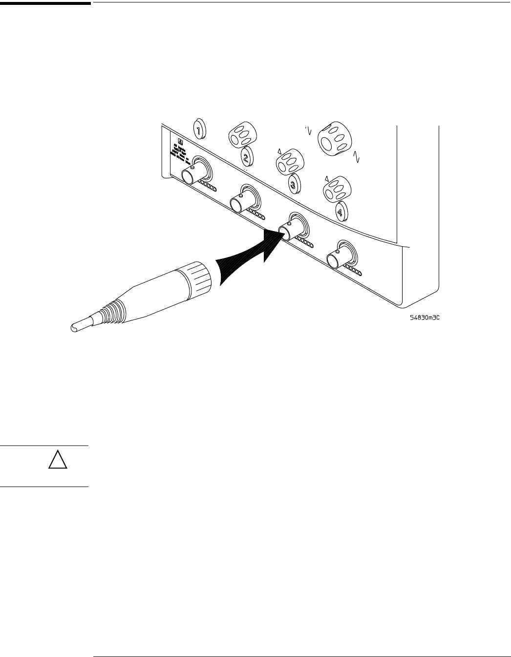
To connect the standard 10073C probes
1 Attach the probe connector to the desired oscilloscope channel or trigger input. Rotate
the BNC connector until it slides on easily and push it straight on. Rotate the locking
ring until it latches into place.
Figure 2-5
Attaching the Probe Connector
2 Connect the probe to the circuit of interest using the browser or other probing
accessories.
3 To disconnect the probe, rotate the locking ring counterclockwise so it unlocks, then
pull the BNC connector body away from the front panel of the oscilloscope.
CAUTION Do not exceed the maximum input voltage rating. The maximum input voltage for 8000 Series
oscilloscopes 50 Ω inputs is 5 Vrms, CAT I. Maximum voltage at 1 MΩ impedance is ±100 V (DC
+ AC) [AC < 10 kHz], CAT I.
!