
Specifications


Table Of Contents
- General Information
- Preparing for Use
- To inspect package contents
- To connect power
- To connect the mouse, keyboard, LAN, printer, and GPIB cable
- To connect the standard 10073C probes
- To connect optional InfiniiMax oscilloscope probes
- To connect the digital probe
- Digital probe lead set
- To tilt the oscilloscope upward for easier viewing
- To turn on the oscilloscope
- To turn off the oscilloscope
- To verify basic oscilloscope operation
- Installing application programs on Infiniium
- Changing Windows System Settings
- To clean the oscilloscope
- Testing Performance
- Calibrating and Adjusting
- Troubleshooting
- To install the fan safety shield
- To troubleshoot the oscilloscope
- Primary Trouble Isolation
- No Display Trouble Isolation
- To check the backlight inverter voltages
- To check the display board video signals
- Power Supply Trouble Isolation
- To check probe power outputs
- To Check the keyboard
- To check the LEDs
- To check the motherboard, CPU, and RAM
- To setup the BIOS
- To troubleshoot the acquisition system
- Software Revisions
- Replacing Assemblies
- To return the oscilloscope to Agilent Technologies for service
- To remove and replace the top cover
- To remove and replace the bottom sleeve
- To disconnect and connect Mylar flex cables
- To remove and replace the CD-ROM drive
- To remove and replace the AutoProbe assembly
- To remove and replace the internal digital input cable (MSO models only)
- To remove and replace the backlight inverter board
- To remove and replace the front panel assembly
- To remove and replace the keyboard, touch screen, and flat-panel display assemblies
- To remove and replace the acquisition board assembly
- To remove and replace the PCI bridge board
- To remove and replace the display board
- To remove and replace the hard disk drive
- To remove and replace the motherboard
- To replace the Intel motherboard with the ADLINK motherboard
- To remove and replace the power supply
- To remove and replace the fan controller board
- To remove and replace a fan
- To remove and replace the probe power and control assembly
- Replaceable Parts
- Theory of Operation
- Index
Chapter 2: Preparing for Use
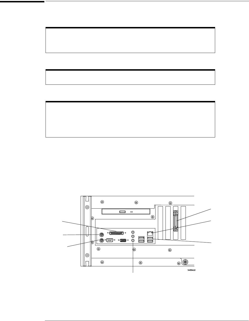
To connect the mouse, keyboard, LAN, printer, and GPIB cable
24
To connect the mouse, keyboard, LAN, printer, and GPIB cable
Mouse. Plug the mouse into the mouse connector on the back panel of the oscilloscope.
Keyboard. Plug the keyboard cable into the keyboard connector on the back panel of the oscilloscope.
LAN Cable. Connect your LAN cable to the RJ-45 connector on the back panel of the oscilloscope.
Printer Cable. If you have a USB printer, you will need to connect its cable to one of the four USB ports on the
rear panel, or to the USB port on the front panel.
If you have a parallel printer, you will need to connect its parallel printer cable to the Parallel
Printer connector on the oscilloscope.
GPIB Cable. If you will be controlling the oscilloscope through the GPIB, attach your GPIB cable to the GPIB
connector on the rear of the oscilloscope.
Figure 2-4
Back Panel
Note: Your instrument’s rear panel configuration may differ from this diagram. Connect the cables based on your instrument’s
configuration.
While you can operate many oscilloscope functions using only the front-panel keys and
knobs, you will need the mouse to access advanced oscilloscope functions through the
graphical interface, or to find out more about the oscilloscope through the built-in
information system.
A keyboard must be plugged into the oscilloscope before the Windows operating system
has started booting.
Depending on your building’s LAN configuration, you may need to set up the
oscilloscope’s network configuration after connecting the LAN cable to the
oscilloscope. If your building’s network uses DHCP, many parameters will already be
compatible. Before you set up the network configuration, you should exit the
oscilloscope application. If you do not know how to setup the network, see your network
administrator or use the Windows XP on-line help.
Mouse
Keyboard
USB
Ports
GPIB
LAN
Parallel
Printer
Line In
Line Out
Microphone