
Specifications


Table Of Contents
- General Information
- Preparing for Use
- To inspect package contents
- To connect power
- To connect the mouse, keyboard, LAN, printer, and GPIB cable
- To connect the standard 10073C probes
- To connect optional InfiniiMax oscilloscope probes
- To connect the digital probe
- Digital probe lead set
- To tilt the oscilloscope upward for easier viewing
- To turn on the oscilloscope
- To turn off the oscilloscope
- To verify basic oscilloscope operation
- Installing application programs on Infiniium
- Changing Windows System Settings
- To clean the oscilloscope
- Testing Performance
- Calibrating and Adjusting
- Troubleshooting
- To install the fan safety shield
- To troubleshoot the oscilloscope
- Primary Trouble Isolation
- No Display Trouble Isolation
- To check the backlight inverter voltages
- To check the display board video signals
- Power Supply Trouble Isolation
- To check probe power outputs
- To Check the keyboard
- To check the LEDs
- To check the motherboard, CPU, and RAM
- To setup the BIOS
- To troubleshoot the acquisition system
- Software Revisions
- Replacing Assemblies
- To return the oscilloscope to Agilent Technologies for service
- To remove and replace the top cover
- To remove and replace the bottom sleeve
- To disconnect and connect Mylar flex cables
- To remove and replace the CD-ROM drive
- To remove and replace the AutoProbe assembly
- To remove and replace the internal digital input cable (MSO models only)
- To remove and replace the backlight inverter board
- To remove and replace the front panel assembly
- To remove and replace the keyboard, touch screen, and flat-panel display assemblies
- To remove and replace the acquisition board assembly
- To remove and replace the PCI bridge board
- To remove and replace the display board
- To remove and replace the hard disk drive
- To remove and replace the motherboard
- To replace the Intel motherboard with the ADLINK motherboard
- To remove and replace the power supply
- To remove and replace the fan controller board
- To remove and replace a fan
- To remove and replace the probe power and control assembly
- Replaceable Parts
- Theory of Operation
- Index
Chapter 8: Theory of Operation
Block-Level Theory
154
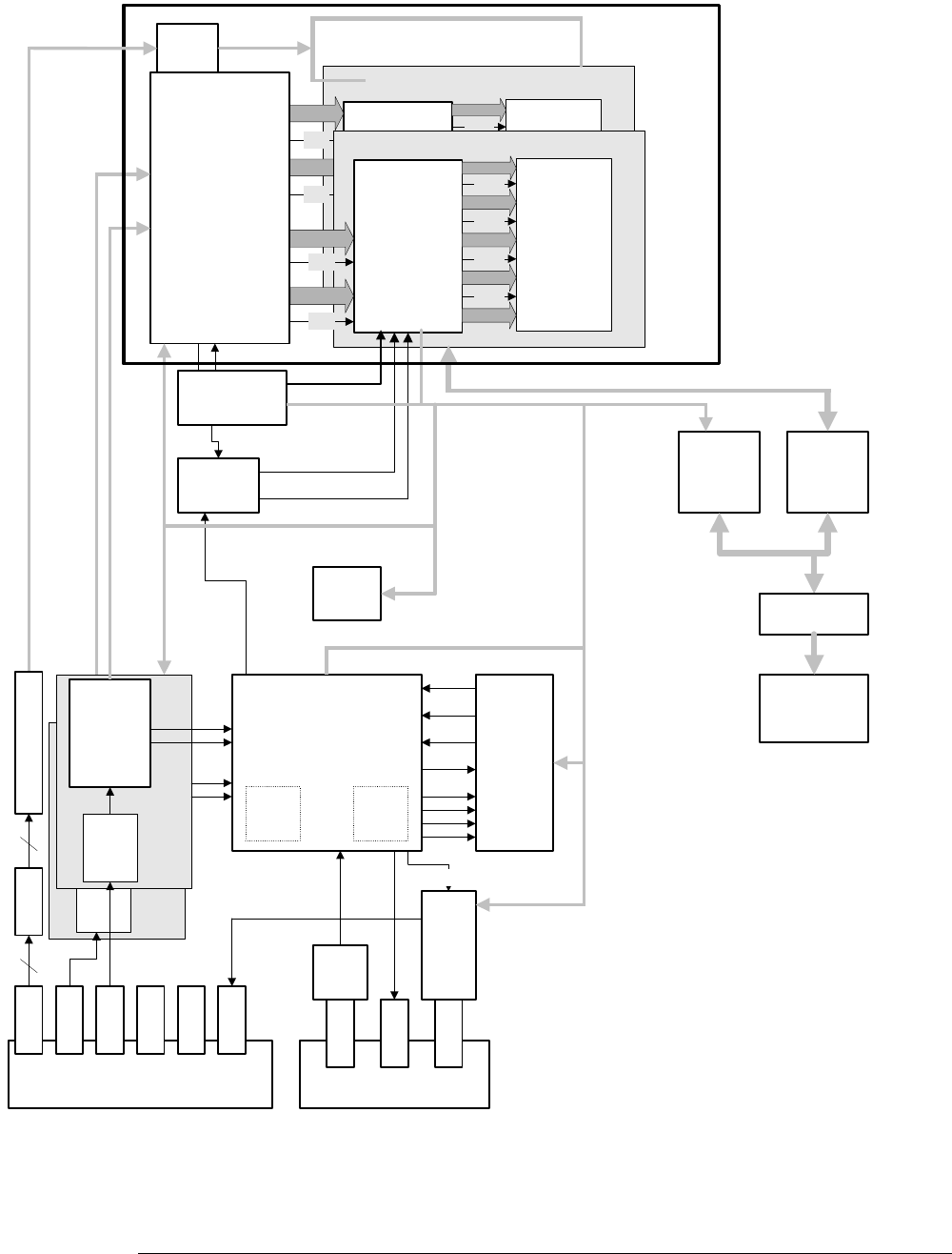
Figure 8-2
Acquisition Block Diagram
Attenuator
Rattler
PreAmp & Dual
Trigger
Comparators
Front End
Upper
Lower
Attenuator
PreAmp & Dual
Trigger
Comparators
Front End
Upper
Lower
INTERFACE
CARD
PCI
Bridge
FPGA
Primary PCI Bus
Ribbon
Cable
Calibrat
or,
Probe
Comp
& Trig
Out
TrigOut
DACS
High Speed Trigger Circuitry
500
MHz
Comp.
Data
Delay
Circuit
Clock
Delay
Circuit
Logic Trigger
Scope Back Panel
AUX IN
AUX OUT
TTL OUT
Scope Front Panel
Probe
Comp
CH 1
CH 2
CH 3
CH 4
CH 1
CH 2
CH 3
CH 4
ATrig
Hold Off
Data
Clock
Zeum
Data
Deceleration &
Processing
LSI Logic ASIC
Acquisition
Memory
8 8Mbit
SGRAMs
8 Bit
8 Bit
CLK
CLK
32 Bit
PHI4
32 Bit
PHI3
32 Bit
PHI2
32 Bit
PHI1
Addr
Data
Deceleration &
Processing
LSI Logic ASIC
Acquisition
Memory
8 8Mbit
SGRAMs
8 Bit
CLK
CLK
32 Bit
PHI4
32 Bit
PHI3
32 Bit
PHI2
32 Bit
PHI1
Addr
8 Bit
4GSa ADC
Trig 1
Trig 2
Fine Gate
Coarse Gate
Reference Clock
Generation
Interpolator
Sys
Trig
Secondary PCI Bus
CH 1 & 2
Digital 0-15
Acquistion Memory
ADC
Digital
0-15
AttenComparators Preamp
0-15 0-15
54830b10