
Specifications


Table Of Contents
- General Information
- Preparing for Use
- To inspect package contents
- To connect power
- To connect the mouse, keyboard, LAN, printer, and GPIB cable
- To connect the standard 10073C probes
- To connect optional InfiniiMax oscilloscope probes
- To connect the digital probe
- Digital probe lead set
- To tilt the oscilloscope upward for easier viewing
- To turn on the oscilloscope
- To turn off the oscilloscope
- To verify basic oscilloscope operation
- Installing application programs on Infiniium
- Changing Windows System Settings
- To clean the oscilloscope
- Testing Performance
- Calibrating and Adjusting
- Troubleshooting
- To install the fan safety shield
- To troubleshoot the oscilloscope
- Primary Trouble Isolation
- No Display Trouble Isolation
- To check the backlight inverter voltages
- To check the display board video signals
- Power Supply Trouble Isolation
- To check probe power outputs
- To Check the keyboard
- To check the LEDs
- To check the motherboard, CPU, and RAM
- To setup the BIOS
- To troubleshoot the acquisition system
- Software Revisions
- Replacing Assemblies
- To return the oscilloscope to Agilent Technologies for service
- To remove and replace the top cover
- To remove and replace the bottom sleeve
- To disconnect and connect Mylar flex cables
- To remove and replace the CD-ROM drive
- To remove and replace the AutoProbe assembly
- To remove and replace the internal digital input cable (MSO models only)
- To remove and replace the backlight inverter board
- To remove and replace the front panel assembly
- To remove and replace the keyboard, touch screen, and flat-panel display assemblies
- To remove and replace the acquisition board assembly
- To remove and replace the PCI bridge board
- To remove and replace the display board
- To remove and replace the hard disk drive
- To remove and replace the motherboard
- To replace the Intel motherboard with the ADLINK motherboard
- To remove and replace the power supply
- To remove and replace the fan controller board
- To remove and replace a fan
- To remove and replace the probe power and control assembly
- Replaceable Parts
- Theory of Operation
- Index
Chapter 7: Replaceable Parts
Power Cords
139
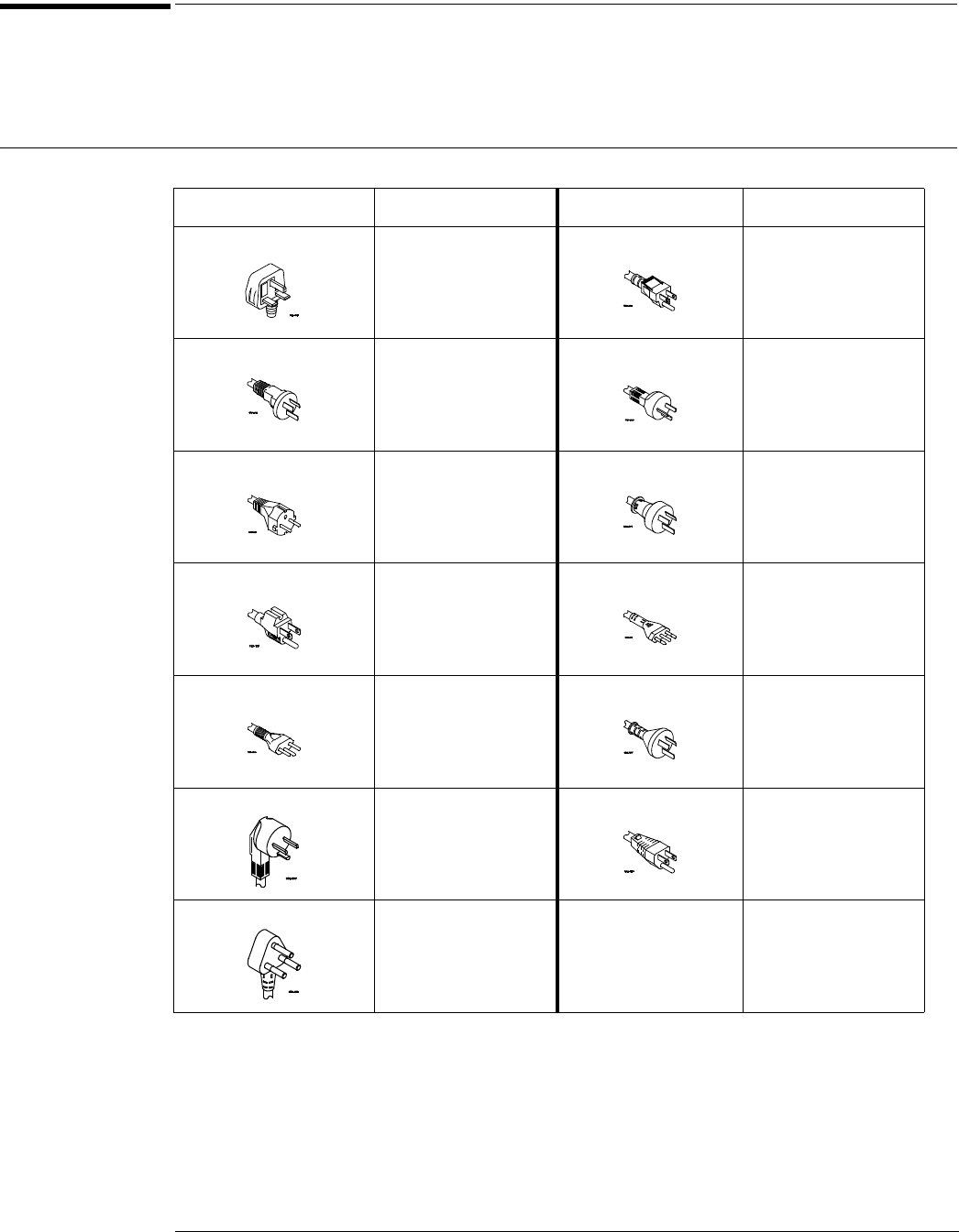
Power Cords
This oscilloscope is equipped with a three-wire power cord. The type of power cord plug shipped
with the oscilloscope depends on the country of destination. The following figure shows option
numbers of available power cords and plug configurations.
Power Cords
Plug Type Cable Part Number Plug Type Cable Part Number
Opt 900 (U.K.) 8121-1579 Opt 918 (Japan) 8121-1603
Opt 901 (Australia) 8121-1581 Opt 919 (Israel) 8121-1662
Opt 902 (Europe) 8121-1580 Opt 920 (Argentina) 8121-1599
Opt 903 (U.S.A.) 8121-1609 Opt 921 (Chile) 8121-1600
Opt 906 (Switzerland) 8121-1602 Opt 922 (China) 8121-1606
Opt 912 (Denmark) 8121-1601 Opt 927 (Thailand) 8120-0674
Opt 917 (India) 8121-1604 Opt 923 (South Africa)
Opt 930 (Brazil)
Opt 931 (Taiwan)
Opt 932 (Cambodia)
8121-1641
8121-1613
8121-1637
8121-1633