
Specifications


Table Of Contents
- General Information
- Preparing for Use
- To inspect package contents
- To connect power
- To connect the mouse, keyboard, LAN, printer, and GPIB cable
- To connect the standard 10073C probes
- To connect optional InfiniiMax oscilloscope probes
- To connect the digital probe
- Digital probe lead set
- To tilt the oscilloscope upward for easier viewing
- To turn on the oscilloscope
- To turn off the oscilloscope
- To verify basic oscilloscope operation
- Installing application programs on Infiniium
- Changing Windows System Settings
- To clean the oscilloscope
- Testing Performance
- Calibrating and Adjusting
- Troubleshooting
- To install the fan safety shield
- To troubleshoot the oscilloscope
- Primary Trouble Isolation
- No Display Trouble Isolation
- To check the backlight inverter voltages
- To check the display board video signals
- Power Supply Trouble Isolation
- To check probe power outputs
- To Check the keyboard
- To check the LEDs
- To check the motherboard, CPU, and RAM
- To setup the BIOS
- To troubleshoot the acquisition system
- Software Revisions
- Replacing Assemblies
- To return the oscilloscope to Agilent Technologies for service
- To remove and replace the top cover
- To remove and replace the bottom sleeve
- To disconnect and connect Mylar flex cables
- To remove and replace the CD-ROM drive
- To remove and replace the AutoProbe assembly
- To remove and replace the internal digital input cable (MSO models only)
- To remove and replace the backlight inverter board
- To remove and replace the front panel assembly
- To remove and replace the keyboard, touch screen, and flat-panel display assemblies
- To remove and replace the acquisition board assembly
- To remove and replace the PCI bridge board
- To remove and replace the display board
- To remove and replace the hard disk drive
- To remove and replace the motherboard
- To replace the Intel motherboard with the ADLINK motherboard
- To remove and replace the power supply
- To remove and replace the fan controller board
- To remove and replace a fan
- To remove and replace the probe power and control assembly
- Replaceable Parts
- Theory of Operation
- Index
Chapter 6: Replacing Assemblies
To remove and replace a fan
135
To remove and replace a fan
Use this procedure to remove and replace a fan. When necessary, refer to other removal
procedures The graphics in this chapter are representative of the oscilloscope at the time of this
printing. Your unit may look different.
WARNING AVOID INJURY!
The fan blades are exposed both inside and outside the chassis. Disconnect the power cable
before working around the fan. Failure to observe these precautions may result in injury.
Use this procedure to remove and replace the fans. When necessary, refer to other removal
procedures.
1
Disconnect the power cable and remove the top and bottom covers.
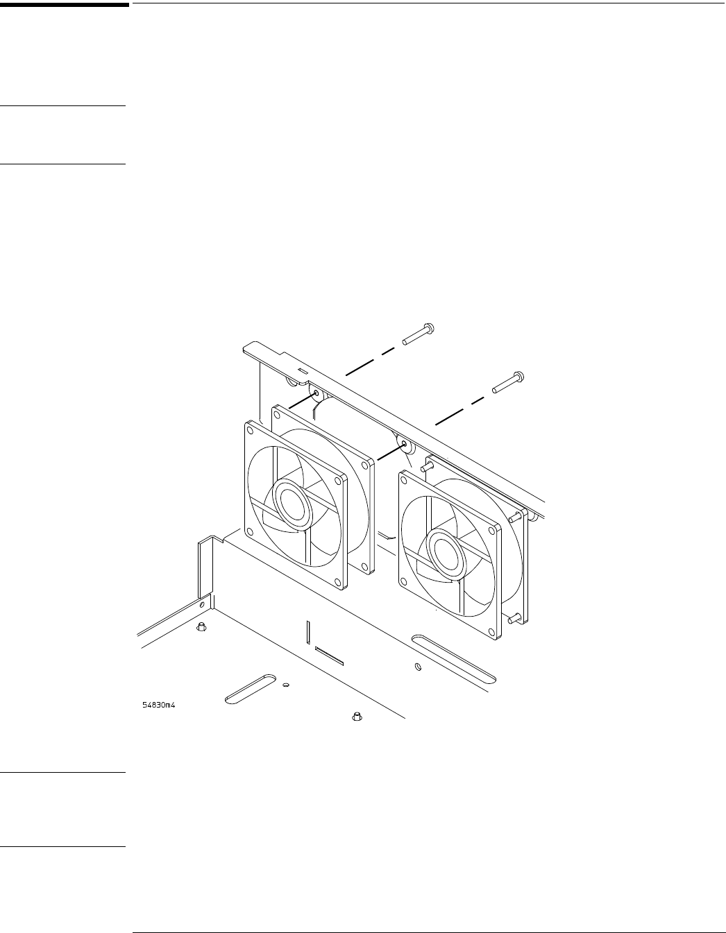
2 Disconnect the fan cable from the fan control board. See Figure 6-34.
3 Remove the four Torx T20 fan screws securing the fan to the chassis.
Figure 6-35
Removing fan fasteners
CAUTION AVOID OVERHEATING THE OSCILLOSCOPE!
When replacing the fan, be sure the direction of the fan air flow is coming from the inside to the
outside of the oscilloscope. Check the flow arrows on the fan and check for proper flow once
power is applied to the oscilloscope. Improper air flow can overheat the oscilloscope.
4
To install the fan, reverse this procedure.
T20 Torx Screws