
Specifications


Table Of Contents
- General Information
- Preparing for Use
- To inspect package contents
- To connect power
- To connect the mouse, keyboard, LAN, printer, and GPIB cable
- To connect the standard 10073C probes
- To connect optional InfiniiMax oscilloscope probes
- To connect the digital probe
- Digital probe lead set
- To tilt the oscilloscope upward for easier viewing
- To turn on the oscilloscope
- To turn off the oscilloscope
- To verify basic oscilloscope operation
- Installing application programs on Infiniium
- Changing Windows System Settings
- To clean the oscilloscope
- Testing Performance
- Calibrating and Adjusting
- Troubleshooting
- To install the fan safety shield
- To troubleshoot the oscilloscope
- Primary Trouble Isolation
- No Display Trouble Isolation
- To check the backlight inverter voltages
- To check the display board video signals
- Power Supply Trouble Isolation
- To check probe power outputs
- To Check the keyboard
- To check the LEDs
- To check the motherboard, CPU, and RAM
- To setup the BIOS
- To troubleshoot the acquisition system
- Software Revisions
- Replacing Assemblies
- To return the oscilloscope to Agilent Technologies for service
- To remove and replace the top cover
- To remove and replace the bottom sleeve
- To disconnect and connect Mylar flex cables
- To remove and replace the CD-ROM drive
- To remove and replace the AutoProbe assembly
- To remove and replace the internal digital input cable (MSO models only)
- To remove and replace the backlight inverter board
- To remove and replace the front panel assembly
- To remove and replace the keyboard, touch screen, and flat-panel display assemblies
- To remove and replace the acquisition board assembly
- To remove and replace the PCI bridge board
- To remove and replace the display board
- To remove and replace the hard disk drive
- To remove and replace the motherboard
- To replace the Intel motherboard with the ADLINK motherboard
- To remove and replace the power supply
- To remove and replace the fan controller board
- To remove and replace a fan
- To remove and replace the probe power and control assembly
- Replaceable Parts
- Theory of Operation
- Index
Chapter 6: Replacing Assemblies
To remove and replace the power supply
133
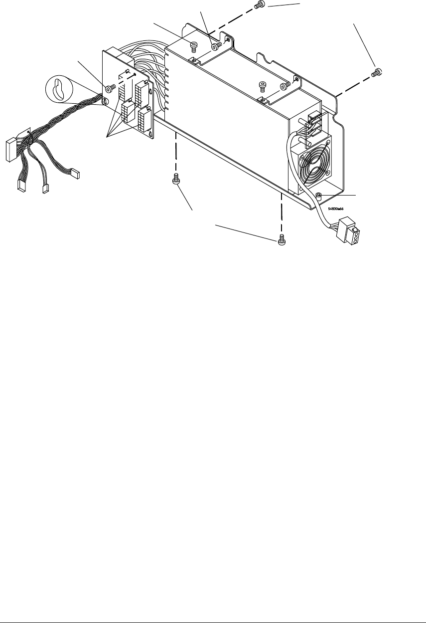
Figure 6-33
Removing the power supply and brackets
4 Disconnect the 4 cables from the power interface board connectors and remove the
Torx T10 screw securing it to the frame.
5 Slide the power interface board up to remove it from the standoffs.
Note the detail of the key-hole slots in See Figure 6-33.
6
Remove the two Torx T10 screws that hold the top support brackets to the chassis.
When re-assembling, torque the two Torx T10 screws to 5 in-lb.
7
Remove the two Torx T20 screws that hold the top support brackets to the power
supply bracket.
When re-assembling, torque the Torx T20 screws to 18 in-lb.
8
Loosen the two Torx T20 screws at both ends of the power supply bracket that secure
the bracket to the frame.
These screws are part of the power supply bracket and can not be removed from the
bracket.
9
Remove the power supply and power supply bracket from the chassis taking care to
avoid damaging any of the cables.
10 Remove the two Torx T20 screws from the side of the power supply bracket.
When re-assembling, torque the Torx T20 screws to 18 in-lb.
11
Remove the two Torx T20 screws from the bottom of the power supply bracket.
When re-assembling, torque the Torx T20 screws to 18 in-lb.
12
Separate the power supply from the power supply bracket.
13 To replace the power supply, reverse the removal procedure.
Power supply
Support
bracket T10
screws (2)
T20 screws
(side bracket)
T20 screws
(bottom
bracket)
T20 screws
(2 bracket to
frame)
Power
interface
board
connectors
T10
screw
Detail of
key-hole
slots (4)
Support
bracket T20
screws (2)