
Specifications


Table Of Contents
- General Information
- Preparing for Use
- To inspect package contents
- To connect power
- To connect the mouse, keyboard, LAN, printer, and GPIB cable
- To connect the standard 10073C probes
- To connect optional InfiniiMax oscilloscope probes
- To connect the digital probe
- Digital probe lead set
- To tilt the oscilloscope upward for easier viewing
- To turn on the oscilloscope
- To turn off the oscilloscope
- To verify basic oscilloscope operation
- Installing application programs on Infiniium
- Changing Windows System Settings
- To clean the oscilloscope
- Testing Performance
- Calibrating and Adjusting
- Troubleshooting
- To install the fan safety shield
- To troubleshoot the oscilloscope
- Primary Trouble Isolation
- No Display Trouble Isolation
- To check the backlight inverter voltages
- To check the display board video signals
- Power Supply Trouble Isolation
- To check probe power outputs
- To Check the keyboard
- To check the LEDs
- To check the motherboard, CPU, and RAM
- To setup the BIOS
- To troubleshoot the acquisition system
- Software Revisions
- Replacing Assemblies
- To return the oscilloscope to Agilent Technologies for service
- To remove and replace the top cover
- To remove and replace the bottom sleeve
- To disconnect and connect Mylar flex cables
- To remove and replace the CD-ROM drive
- To remove and replace the AutoProbe assembly
- To remove and replace the internal digital input cable (MSO models only)
- To remove and replace the backlight inverter board
- To remove and replace the front panel assembly
- To remove and replace the keyboard, touch screen, and flat-panel display assemblies
- To remove and replace the acquisition board assembly
- To remove and replace the PCI bridge board
- To remove and replace the display board
- To remove and replace the hard disk drive
- To remove and replace the motherboard
- To replace the Intel motherboard with the ADLINK motherboard
- To remove and replace the power supply
- To remove and replace the fan controller board
- To remove and replace a fan
- To remove and replace the probe power and control assembly
- Replaceable Parts
- Theory of Operation
- Index
Chapter 6: Replacing Assemblies
To replace the Intel motherboard with the ADLINK motherboard
124
To replace the Intel motherboard with the ADLINK motherboard
When replacing an Intel motherboard with an ADLINK motherboard order the D8104-68700
M880 Motherboard Kit and follow these instructions.
1
Remove the CD-ROM drive using the instructions beginning on page 102.
2 Remove all cables from the PCI cards.
3 Remove all PCI cards from the motherboard.
4 Disconnect all cables from the motherboard.
5 Remove the six 5 mm port lock screws from the rear panel connectors.
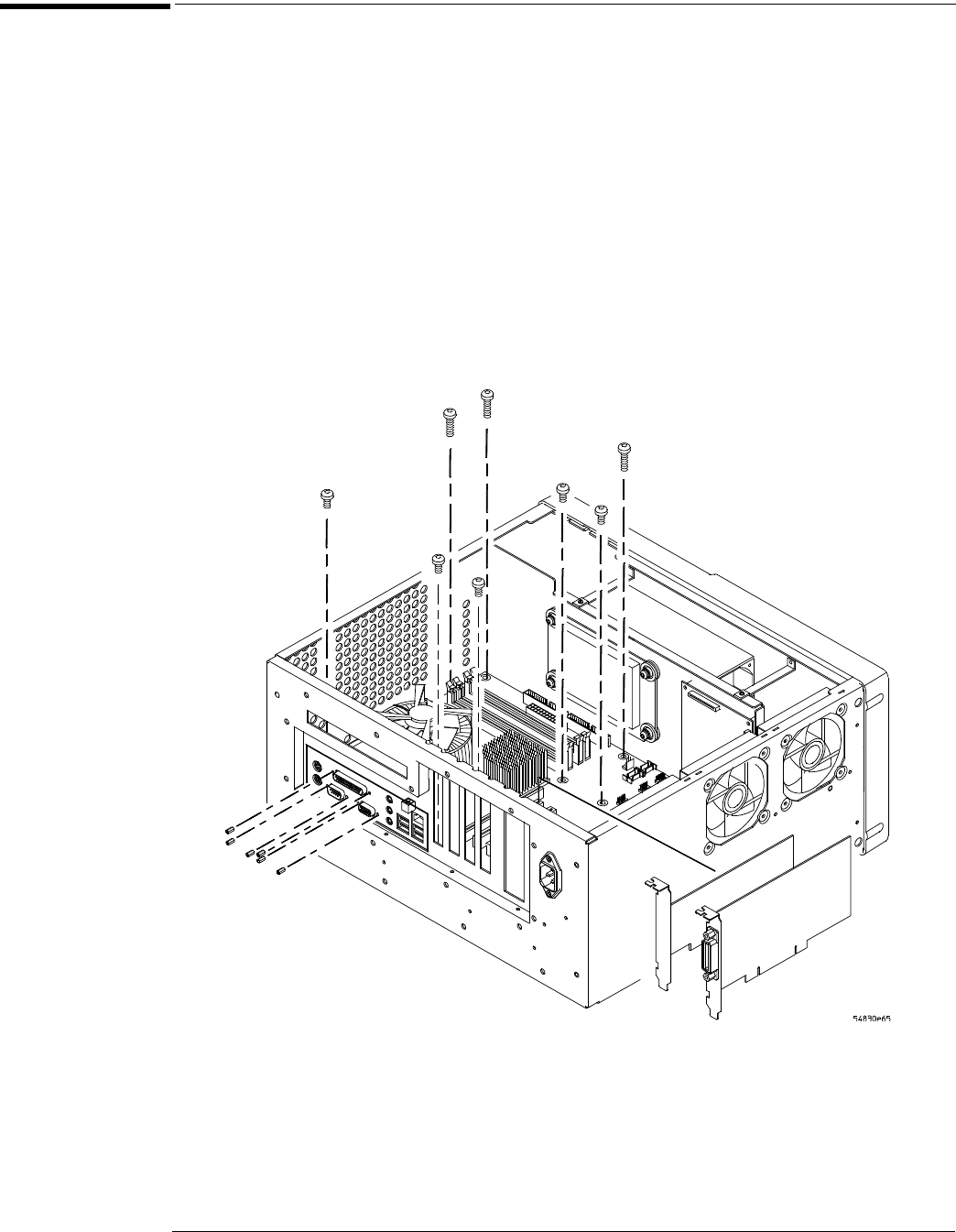
6 Remove the 5 short and 3 long Torx T10 screws holding the motherboard to the ATX
tray.
Figure 6-29
Removing the motherboard
7 Remove the 8 T20 screws holding the tray to the rear panel.
8 Remove the 3 T10 screws holding the filler plate to rear panel and tray.
9 Remove the hard disk drive using the instructions beginning on page 120.
10 Lift tray with old motherboard from rear and slide to clear the rear panel clearing the
three long standoffs under the tray remove the tray from the chassis.
Port lock
screws (6)
Torx T10
screws (8)
PCI cards