
Specifications


Table Of Contents
- General Information
- Preparing for Use
- To inspect package contents
- To connect power
- To connect the mouse, keyboard, LAN, printer, and GPIB cable
- To connect the standard 10073C probes
- To connect optional InfiniiMax oscilloscope probes
- To connect the digital probe
- Digital probe lead set
- To tilt the oscilloscope upward for easier viewing
- To turn on the oscilloscope
- To turn off the oscilloscope
- To verify basic oscilloscope operation
- Installing application programs on Infiniium
- Changing Windows System Settings
- To clean the oscilloscope
- Testing Performance
- Calibrating and Adjusting
- Troubleshooting
- To install the fan safety shield
- To troubleshoot the oscilloscope
- Primary Trouble Isolation
- No Display Trouble Isolation
- To check the backlight inverter voltages
- To check the display board video signals
- Power Supply Trouble Isolation
- To check probe power outputs
- To Check the keyboard
- To check the LEDs
- To check the motherboard, CPU, and RAM
- To setup the BIOS
- To troubleshoot the acquisition system
- Software Revisions
- Replacing Assemblies
- To return the oscilloscope to Agilent Technologies for service
- To remove and replace the top cover
- To remove and replace the bottom sleeve
- To disconnect and connect Mylar flex cables
- To remove and replace the CD-ROM drive
- To remove and replace the AutoProbe assembly
- To remove and replace the internal digital input cable (MSO models only)
- To remove and replace the backlight inverter board
- To remove and replace the front panel assembly
- To remove and replace the keyboard, touch screen, and flat-panel display assemblies
- To remove and replace the acquisition board assembly
- To remove and replace the PCI bridge board
- To remove and replace the display board
- To remove and replace the hard disk drive
- To remove and replace the motherboard
- To replace the Intel motherboard with the ADLINK motherboard
- To remove and replace the power supply
- To remove and replace the fan controller board
- To remove and replace a fan
- To remove and replace the probe power and control assembly
- Replaceable Parts
- Theory of Operation
- Index
Chapter 6: Replacing Assemblies
To remove and replace the keyboard, touch screen, and flat-panel display assemblies
115
8
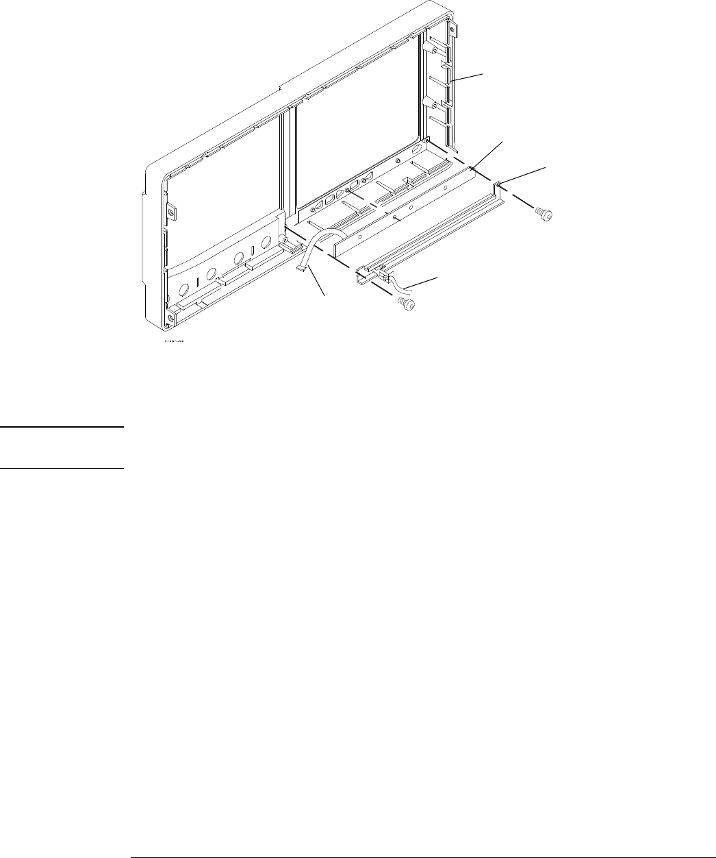
To remove the cursor keyboard, remove the two Torx T10 screws that secure the cursor
keyboard bracket then lift the cursor keyboard directly out of the front casting.
Figure 6-21
Removing the cursor keyboard
9 To reassemble the front panel assembly, reverse the above procedure.
The cursor keyboard has holes that fit over locating pins in the front panel casting.
CAUTION PREVENT GLASS BREAKAGE!
Use care when handling the touch screen and the flat-panel display to prevent glass breakage.
Inspect the inside surfaces of the touch screen and the flat-panel display closely for dust,
smudges, and fingerprints. Viewing these with line-of-sight 45 degrees to the surface is the best
method for seeing subtle flaws. Clean the surfaces of the touch screen with glass cleaner and
lint-free lens paper before re-assembly. Clean the front of the FPD monitor by applying the glass
cleaner to the lint-free lens paper or soft lens cloth. Do not apply glass cleaner directly to the
FPD monitor.
Cursor keyboard
cable
Cursor keyboard bracket
Cursor keyboard
Aux Out SMB cable
Front casting