
Specifications


Table Of Contents
- General Information
- Preparing for Use
- To inspect package contents
- To connect power
- To connect the mouse, keyboard, LAN, printer, and GPIB cable
- To connect the standard 10073C probes
- To connect optional InfiniiMax oscilloscope probes
- To connect the digital probe
- Digital probe lead set
- To tilt the oscilloscope upward for easier viewing
- To turn on the oscilloscope
- To turn off the oscilloscope
- To verify basic oscilloscope operation
- Installing application programs on Infiniium
- Changing Windows System Settings
- To clean the oscilloscope
- Testing Performance
- Calibrating and Adjusting
- Troubleshooting
- To install the fan safety shield
- To troubleshoot the oscilloscope
- Primary Trouble Isolation
- No Display Trouble Isolation
- To check the backlight inverter voltages
- To check the display board video signals
- Power Supply Trouble Isolation
- To check probe power outputs
- To Check the keyboard
- To check the LEDs
- To check the motherboard, CPU, and RAM
- To setup the BIOS
- To troubleshoot the acquisition system
- Software Revisions
- Replacing Assemblies
- To return the oscilloscope to Agilent Technologies for service
- To remove and replace the top cover
- To remove and replace the bottom sleeve
- To disconnect and connect Mylar flex cables
- To remove and replace the CD-ROM drive
- To remove and replace the AutoProbe assembly
- To remove and replace the internal digital input cable (MSO models only)
- To remove and replace the backlight inverter board
- To remove and replace the front panel assembly
- To remove and replace the keyboard, touch screen, and flat-panel display assemblies
- To remove and replace the acquisition board assembly
- To remove and replace the PCI bridge board
- To remove and replace the display board
- To remove and replace the hard disk drive
- To remove and replace the motherboard
- To replace the Intel motherboard with the ADLINK motherboard
- To remove and replace the power supply
- To remove and replace the fan controller board
- To remove and replace a fan
- To remove and replace the probe power and control assembly
- Replaceable Parts
- Theory of Operation
- Index
Chapter 6: Replacing Assemblies
To remove and replace the backlight inverter board
107
To remove and replace the backlight inverter board
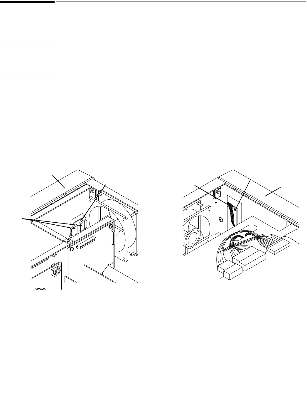
Use this procedure to remove and replace the backlight inverter board. When necessary, refer
to other removal procedures. The graphics in this chapter are representative of the oscilloscope
at the time of this printing. Your unit may look different.
WARNING SHOCK HAZARD!
The backlight inverter assembly, which is mounted at the front corner of the oscilloscope near
the flat-panel display, operates at high voltages from 300-1 kV ac
rms
. DO NOT handle this
assembly while it is in operation.
1
Disconnect the power cable and remove the top and bottom covers.
2 Disconnect the two backlight cables from the top of the backlight inverter board.
3 Disconnect the backlight primary cable from the bottom of the backlight inverter
board.
4 Using a long Torx T10 driver, remove the two Torx T10 screws that secure the backlight
inverter board to the chassis.
5 Lift the backlight inverter board out through the top of the chassis.
6 To replace the backlight inverter board, reverse this procedure.
Figure 6-12
Removing the backlight inverter board
Backlight
inverter
cable
LCD power
cables
Bottom edge
front panel
Top edge
front panel
T10 torx screw
T10 torx
screw