
Programming instructions


13
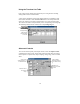
AM or FM Modulation
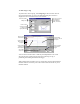
To precisely generate AM or FM output signals, either click the Modulation
icon, or select the Modulation command in the Tests menu.
AM or FM output waveforms consist of a carrier signal (the fundamental) and a
modulation signal. The voltage and frequency of the carrier signal is defined in
the Output Control section of the Main window. Only the modulation signal is
defined in this dialog box.
Click
Modulation signals are comprised of from one to 20 individually programmed
steps that may be combined into a modulation sequence and then run. Each step
programs the modulation signal for the duration of the step. The amplitude and
frequency of the modulation signal may be constant, swept linearly, or swept
logarithmically from the starting value to a stop value. The sweep period is
programmed in seconds.
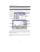
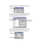
Transfer Time for UPS
To measure the transfer time of switching devices such as UPSs, select Transfer
Time Test in the Tests menu. Transfer time is defined as the time it takes a UPS
for example to go from online-operation to battery backup operation when the ac
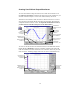
line fails. The entire transfer time period must appear in the Main window for the
measurement to be valid.
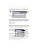
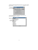
The transfer time results appear in the Test Results area of the dialog box. The
transfer time is displayed in seconds. When you close the Transfer Time Test
dialog box, you will be able to see both the output of the ac source and the
output of the UPS in the waveform display area.
Enter
parameters for
modulation
signal.
Specify dropout time to
simulate an ac line failure.
Lets you edit
# of steps in
modulation
profile.
Results of Transfer
Time test appear
h
Runs the Transfer
Time test.
Minimum pulse width
measured at UPS that
qualifies as ending the
transfer time
p
eriod.
Specify voltage level of ac
source during the dropout
period.
Specify the output phase
angle at which the output o
f
the ac source dro
p
s out.
Specify voltage level that
determines if UPS has
recovered.