Quick Start Guide Agilent Technologies AC Source/ Power Analyzer Graphical User Interface for Windows 95-98, 2000 and Windows NT 4.
Contents Description ...........................................................................................................3 System Requirements ...........................................................................................3 Installing and Running the Software.....................................................................4 Configuring the I/O ..............................................................................................4 Performing Basic Operations....................
Description What the GUI Will Do The Agilent AC Source Graphical User Interface (GUI) is an easy to use soft front panel for the Agilent Technologies 6800-series AC Power Source/Analyzers. With it, you can: a Control output and measurement functions from a single screen. a View an oscilloscope-like display of actual output waveforms. a View the harmonic content of the output waveform. a Easily generate complex output transients and user-defined waveforms by clicking and dragging the mouse.
Installing and Running the Software NOTE: Before running the Agilent AC Source GUI, you must have installed and connected your ac source to the pc using the appropriate interface cable. If you are using a National Instruments GPIB interface, you must have the appropriate card installed and configured on your pc. If you are using an Agilent GPIB interface card, you must also have the appropriate 32-bit SICL library drivers installed on your pc. 1. 2. 3.
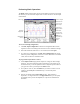
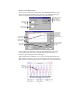
Performing Basic Operations The Main window appears when you first run the Agilent AC Source GUI. From this window you can control the output of the ac source as well as view all output measurements. Click to start a t Click to configure measurements. Turn on the ac source output. Click Enter to apply all values to the output. Waveform display area. Set the output to 120Vac. Use F/G keys or keyboard entry.
a Select Output On to enable the output of the unit. Select Output Off to turn the output off. Note that the selected waveshape will not appear on the Main window unless you click the Measure button. To view output measurements, a Select the Config Measurements command in the Measure menu. Select the Configure Waveform Display folder. Specify type of measurement. Select units for harmonic graph axes Only applies to units with the AUX channel option.
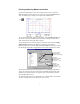
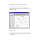
Printing and Saving Measurement Data To print the measurement screen, click on either the Print icon or select the Print command in the File menu. You can preview and print the Main window only. The following is a sample preview/print of the Main window: Click To save the waveform that appears in the display, select Save Waveform in the File menu. This saves the displayed waveform as an ASCII file, which can be easily imported into other application programs.
Exporting Measurement Data to Microsoft Excel To export the measurement display and all measured data from the ac source directly to a Microsoft Excel spreadsheet, select the Send Excel Chart command in the Edit menu. The application only supports Microsoft Excel 97 and Microsoft Excel 2000. The following is a sample Microsoft Excel spreadsheet with the exported data. Sample Tests The following sample tests are provided with the Agilent AC Source Graphical User Interface.
Inrush Current Measurement To perform an inrush current measurement, select Inrush Current in the Tests menu. The test uses the parameters that you enter in the following dialog box. This box is displayed on the screen when the test is first selected. Click here to continue. This displays the Output Transient Editor. (see below) Enter a Final Line Voltage value Enter a turn-on phase angle. Output goes to 120 Vac @ 90° phase angle. (Drag point to adjust amplitude.
AC Line Dropout To perform an ac line dropout, select Dropout in the Tests menu. The test uses the parameters that you enter in the following dialog box. This box is displayed on the screen when the test is first selected. Click here to continue. This displays the Output Transient Editor. Enter the number of dropout cycles Enter the dropout voltage value Check to enable measurement trigger. Enter a starting phase angle. Step #3, output voltage returns to 120 Vac. (Drag point to adjust amplitude .
AC Line Surge or Sag To perform an ac line surge/sag, select Surge/Sag in the Tests menu. The test uses the parameters that you enter in the following dialog box. This box is displayed on the screen when the test is first selected. Click here to continue. This displays the Output Transient Editor. (see below) Enter a Surge/Sag Voltage value Enter T1 value. Also enter T2 and T3 values in the appropriate fields. Start of output measurement Output voltage returns to 120 Vac at step #3.
Telephone Ring Generator CAUTION: This test is only designed to test telephone ringer circuits. Do not use this test to power any device that requires ac input power. To produce an output signal to test telephone ringers, select Ring Generator in the Tests menu. The test uses the parameters that appear in the dialog box that is displayed on the screen when the test is first selected. Click here to continue. This displays the Output Transient Editor.
AM or FM Modulation To precisely generate AM or FM output signals, either click the Modulation icon, or select the Modulation command in the Tests menu. AM or FM output waveforms consist of a carrier signal (the fundamental) and a modulation signal. The voltage and frequency of the carrier signal is defined in the Output Control section of the Main window. Only the modulation signal is defined in this dialog box. Lets you edit # of steps in modulation profile. Click Enter parameters for modulation signal.
RTCA/DO-160 for Airborne Equipment To test airborne equipment according to the RTCA/DO-160 specification, select RTCA/DO-160 in the Tests menu. Only single-phase equipment is supported, three-phase equipment is not supported. Check the test items to include in the test Select ac or dc input power. Select the test category (A, B, E, or Z) Select the Pass/Fail criteria for the test items. Indicates the total estimated time of test. Sends completed test results to the default printer.
Creating User-Defined Output Waveforms To create user-defined voltage waveforms, select either the waveform icon or the Arbitrary Waveforms command in the Source menu. This window lets you edit basic waveform shapes to create a user-defined arbitrary waveform. Waveforms can be edited in either waveform or harmonic format. To create or edit a waveform, the Display Mode must match the Edit Mode. Download the completed waveform to the ac source.
Using the Transient List Table Four of the previous sample tests introduced you to using the click and drag editing features of the Transient Editor. A more precise method of creating and editing transients is available by using the Transient List table. Click the View Table button in the Output Transient editor. The Transient List table is simply another view of the transient editor. The values in the table correspond exactly to the corresponding transient graph.
To program Output impedance, select the Impedance command in the Source menu. You can program real or reactive impedance. These controls are not available on all ac source models. Enable ouput impedance control Enter impedance values To configure output measurements, select the Config Measurements command in the Measure menu. Then select the Configure Measurements folder. You can select what measurements appear in the measurement summary area and how often the summary measurements are updated.
To display the maximum programmable values for the ac source that is presently being controlled by the Agilent AC Source GUI, select the Ratings command in the Source menu. Displays maximum programmable settings of ac source. To view the SCPI instrument commands sent to the ac source, select Instrument Commands in the View menu. Select command viewing options. View the programming commands.
Warranty This Agilent Technologies software product is warranted against defects in materials and workmanship for a period of 90 days from date of delivery. During the warranty period, Agilent Technologies will, at its option either repair or replace parts which prove to be defective.
Manual part number: 5962-8191 5 Printed in USA, February 1999 Updated June 2006