User’s Guide AC Power Solutions Agilent Models 6814B, 6834B, and 6843A For instruments with Serial Numbers: Agilent 6814B: 3601A-00101 through 00270 US36010101-up Agilent 6834B: 3601A-00101 through 00140 US36010101-up Agilent 6843A: 3540A-00101 through 00140 US35400101-up Agilent Part No. 5962-0887 Microfiche No 5962-0888 Printed in U.S.A.
Warranty Information CERTIFICATION Agilent Technologies certifies that this product met its published specifications at time of shipment from the factory. Agilent Technologies further certifies that its calibration measurements are traceable to the United States National Bureau of Standards, to the extent allowed by the Bureau’s calibration facility, and to the calibration facilities of other International Standards Organization members.
Safety Summary The following general safety precautions must be observed during all phases of operation of this instrument. Failure to comply with these precautions or with specific warnings elsewhere in this manual violates safety standards of design, manufacture, and intended use of the instrument. Agilent Technologies assumes no liability for the customer’s failure to comply with these requirements. WARNING: LETHAL VOLTAGES Ac sources can supply 425 V peak at their output.
SAFETY SYMBOLS Direct current Alternating current Both direct and alternating current Three-phase alternating current Earth (ground) terminal Protective earth (ground) terminal Frame or chassis terminal Terminal is at earth potential. Used for measurement and control circuits designed to be operated with one terminal at earth potential.
Declaration Page DECLARATION OF CONFORMITY according to ISO/IEC Guide 22 and EN 45014 Manufacturer’s Name: Manufacturer’s Address: Agilent Technologies, Inc. 140 Green Pond Road Rockaway, New Jersey 07866 U.S.A.
Acoustic Noise Information Herstellerbescheinigung Diese Information steht im Zusammenhang mit den Anforderungen der Maschinenläminformationsverordnung vom 18 Januar 1991. * Schalldruckpegel Lp <70 dB(A) * Am Arbeitsplatz * Normaler Betrieb * Nach EN 27779 (Typprüfung). Manufacturer’s Declaration This statement is provided to comply with the requirements of the German Sound Emission Directive, from 18 January 1991.
Table of Contents Warranty Information Safety Summary Declaration Page Acoustic Noise Information Printing History Table of Contents 1. GENERAL INFORMATION Document Orientation Safety Considerations Options, Accessories, and User Replaceable Parts Description Capabilities Front Panel/Remote Operation Output Characteristic Ranges Output VA Capability 2.
4.
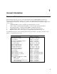
1 General Information Document Orientation This manual describes the operation of the Agilent Technologies 6814B/6834B/6843A AC Power Solutions. These units will be referred to as "ac sources" throughout this manual. Operation of the Agilent 6843A is described for normal mode operation only.
1 - General Information Safety Considerations This ac source is a Safety Class 1 instrument, which means it has a protective earth terminal. That terminal must be connected to earth ground through a power source equipped with a ground receptacle. Refer to the Safety Summary page at the beginning of this guide for general safety information. Before installation or operation, check the ac source and review this guide for safety warnings and instructions.
General Information - 1 Description The ac source combines three instruments in one unit as shown in the following figure. The function generator produces waveforms with programmable amplitude, frequency, and shape. The power amplifier amplifies the function generator signal to produce the ac power for your application. The measurement functions range from a simple readback of rms voltage and current, to sophisticated capabilities such as waveform analysis.
1 - General Information ♦ ♦ ♦ ♦ ♦ ♦ ♦ • Additional total power and neutral current measurements in the three-phase model. • All measurements made with 16-bit resolution. Trigger In and Trigger Out for synchronizing transient events or measurements with external signals. Front panel control with 14-character vacuum fluorescent display, keypad, and rotary pulse generators for voltage and frequency settings. Built-in GPIB and RS-232 interface programming with SCPI command language.
General Information - 1 Vrms 300 V 150 V See Figure 1-3 Irms 0 5A 15A 10A 16A 10A (6834B 3phase) 30A (6834B 1phase) 20A (6814B) 32A (6843A) Figure 1-2. AC Source Output Characteristic (in real-time mode) Output VA Capability The output capability of each output phase is limited by VA (volts-amps) rather than power (watts). The amount of VA available to a load can be determined by examining figure 1-3, the output power curve. This curve rates the available VA versus output voltage.
2 Installation Inspection Damage When you receive your ac source, inspect it for any obvious damage that may have occurred during shipment. If there is damage, notify the shipping carrier and the nearest Agilent Sales and Support Office immediately. The list of Agilent Sales and Support Offices is at the back of this guide. Warranty information is printed in the front of this guide.
2 - Installation Location Refer to the Safety Summary page at the beginning of this manual for safety-related information about environmental conditions. WARNING: Agilent 6814B units weigh 79.5 kg (175 lbs.) Agilent 6834B/ 6843A units weigh 87.7 kg (193 lbs.) Obtain adequate help when moving the unit or mounting the unit in the rack. Bench Operation The outline diagram in figure 2-1 gives the dimensions of your ac source. The feet may be removed for rack mounting.
Installation - 2 Input Connections Input Source and Line Fuse The ac source requires a 3-phase power service that provides 7350 VA (6000 W) maximum. The power service should have a current rating greater than or equal to the ac source’s circuit breaker rating. The ac source has a delta input (no neutral connection) and will accept power from either delta (triangle) or wye (star) services. CAUTION: Two input voltage ranges are available (see "AC Input Ratings" in appendix A).
2 - Installation 2 CAUTION 7 LINE RATING WARNING F1 F2 WARNING F3 L1 L2 L3 3 1 6 4 5 10cm (4 in.) Figure 2-2. Connecting the Power Cord Output Connections The power output terminal block has a termination for each of the output phases (φ1, φ2, φ3 ) and a floating neutral line (COM) for the phase return connections. A separate earth ground terminal ( ⊥) is located near the output terminals. Figure 2-3.
Installation - 2 NOTE: To minimize the possibility of instability on the output, keep load leads as short as possible bundle or twist the leads tightly together to minimize inductance Wire Considerations Current Ratings Fire Hazard To satisfy safety requirements, load wires must be large enough not to overheat when carrying the maximum short-circuit current of the ac source.
2 - Installation Remote Sense Connections Under normal operation, the ac source senses the output voltage at the output terminals on the back of the unit. External sense terminals are available on the back of the unit that allow the output voltages to be sensed at the load, compensating for impedance losses in the load wiring. As shown in the following figure: ♦ Connect the phase 1 (φ1) through phase 2 (φ) sense terminals to the side of the load that connects to the corresponding output terminal.
Installation - 2 OVP Considerations The overvoltage protection circuit senses voltage near the output terminals, not at the load. Therefore the signal sensed by the OVP circuit can be significantly higher than the actual voltage at the load. When using remote sensing, you must program the OVP trip voltage high enough to compensate for the voltage drop between the output terminals and the load.
2 - Installation In example B, the FLT output of one unit is connected to the INH input of another unit. A fault condition in one of the units will disable all of them without intervention either by the controller or external circuitry. The controller can be made aware of the fault via a service request (SRQ) generated by the Questionable Status summary bit. NOTE: Diagram is correct for 6814B/6834B. Connector and connections are rotated 180 degrees for 6843A FLT INH + - + + - + - ....
Installation - 2 RS-232 Interface The ac source provides an RS-232 programming interface, which is activated by commands located under the front panel Address key. When the RS-232 interface is selected, the GPIB interface is disabled. NOTE: Sending or receiving data over the RS-232 interface when not configured for REMOTE operation can cause unpredictable results. Always make sure the ac source is configured for remote operation when using the RS-232 interface.
2 - Installation Hardware Handshake The RS-232 interface uses the DTR (data terminal ready) line as a holdoff signal to the bus controller. When DTR is true, the bus controller may send data to the ac source. When DTR goes false, the bus controller must stop sending data within 10 characters, and must not send any more data until DTR goes true again. The ac source sets DTR false under two conditions. 1. When the input buffer is full (approximately 100 characters have been received), it will set DTR false.
3 Turn-On Checkout Introduction Successful tests in this chapter provide a high degree of confidence that the ac source is operating properly. For verification tests, see appendix B. Complete performance tests are given in the Service Guide. NOTE: This chapter provides a preliminary introduction to the ac source front panel. See Chapter 4 for more details. Preliminary Checkout WARNING: LETHAL VOLTAGES. Ac sources can supply 425 V peak at their output.
3 - Turn-On Checkout Using the Keypad (shift) p Ë And and q Ì É Some of the front panel keys perform two functions, one labeled in black and the other in blue. You access the blue function by first pressing the blue shift key. Release the key after you press it. The Shift annunciator will be on, indicating that you have access to any key’s shifted function. These keys let you scroll up and down through the choices in the presently selected function menu.
Turn-On Checkout - 3 Make sure that the unit is turned off, and make the following connections to the output. If you are verifying a single phase source, you only need to connect one bulb. Figure 3-1.Verification Connections Procedure Display Explanation 1. Turn the unit on. Meter mode Meter mode is active and the Dis annunciator should be on. 2. Press the Voltage key. VOLT 0.00 Display indicates the default settings. If you are verifying a three phase source, all phase annunciators should be on.
3 - Turn-On Checkout Procedure Display Explanation 11. Press or ô and scroll to the VOLT:PROT item VOLT:PROT 500 Display shows the overvoltage protection trip voltage for your unit. The overvoltage protection voltage is programmed in peak, not rms volts. 12. Press 1, 6, 0, Enter VOLT:PROT 160 Programs the OVP to 160 Vpeak, the rms value of which is less than the previously set rms voltage.
Turn-On Checkout - 3 In Case of Trouble Error Messages Ac source failure may occur during power-on selftest or during operation. In either case, the display may show an error message that indicates the reason for the failure. Selftest Errors Pressing the Shift and Error keys will show the error number. Selftest error messages appear as: ERROR , where "n" is a number listed in the following table. If this occurs, turn the power off and then back on to see if the error persists.
4 Front panel Operation Introduction Here is what you will find in this chapter: ♦ ♦ a complete description of the front panel controls front panel programming examples that describe: • how to program the output voltage and frequency • how to measure the output • how to program the output pulses and lists • how to trigger output changes Front Panel Description Figure 4-1.
4 - Front Panel Operation j Display k Annunciators l Voltage/ Frequency 14-character vacuum fluorescent display for showing programmed commands and measured values. Annunciators light to indicate operating modes and status conditions: φ1, φ2, φ3 Phase 1, 2, or 3 is being controlled or metered. CV The ac source output is in constant-voltage mode. CC The ac source output is in constant-current mode. Unr The ac source output is in an unregulated state. Dis The ac source output is disabled (off).
Front Panel Operation - 4 System Keys Refer to the examples later in this chapter for more details on the use of these keys. SYSTEM Local Error Address Save Recall Figure 4-2. System Keys This is the blue, unlabeled key, which is also shown as Shift in this guide. Pressing this key accesses the alternate or shifted function of a key (such as ERROR ). Release the key after you press it. When the Shift annunciator is lit, the shifted keys are active.
4 - Front Panel Operation Function Keys Refer to the examples later in this chapter for more details on the use of these keys. FUNCTION Harmonic Meter Output Input Index Current Voltage Phase Index Freq Status Protect Shape Trigger List Trigger Control Pulse Phase Select Output on/off Figure 4-3. Function Keys Immediate Action Keys Immediate action keys immediately execute their corresponding function when pressed.
Front Panel Operation - 4 Scrolling Keys Scrolling keys let you move through the commands in the presently selected function menu. ô Shift pIndex qIndex ¯ ° Shift These scroll keys let you move through the choices in a command list. Press q to bring up the next command in the list. Press p to go back to the previous command in the list. Function menus are circular; you can return to the starting position by continuously pressing either key.
4 - Front Panel Operation Shift Harmonic Press this key to access the harmonic menu list Display Measurement A I:MAG: ° I:PHASE: V V:MAG: ° V:PHASE: N:MAG: ° N:PHASE: ° CURR:THD ° VOLT:THD current harmonic magnitude current harmonic phase voltage harmonic magnitude voltage harmonic phase neutral current harmonic magnitude neutral current harmonic phase current total % harmonic disto
Front Panel Operation - 4 Shift Phase Press this key to access the phase menu list. Display Command Function PHASE PHASE:T PHASE:M Press this key to access the shape menu list.
4 - Front Panel Operation Protection and Status Control Keys The Protect and Status keys control the protection functions and status registers of the ac source. Refer to Chapter 4 of the Programming guide for more information on the status registers. Protect Press this key to access the protection menu list. Display Command Function PROT:CLEAR Clear the status registers of all activated protection signals. The fault causing a signal must be corrected or removed before the register can be cleared.
Front Panel Operation - 4 Trigger and List Control Keys The Trigger Control key controls output transient triggers. The List key controls the generation of output lists. A list can contain up to 100 points, each of which can specify an output change (or transient). Refer to Chapter 4 of the Programming Guide for more information about programming triggers and lists. Trigger Control Press this key to access the trigger control menu list.
4 - Front Panel Operation Entry Keys Refer to the examples later in this chapter for more details on the use of these keys. ENTRY Calibration 7 8 9 4 5 6 1 2 3 - Clear Entry E 0 Enter . Figure 4-4. Entry Keys Ë 0 Ì − 9 . These keys let you scroll through choices in a parameter list that apply to a specific command. Parameter lists are circular; you can return to the starting position by continuously pressing either key.
Front Panel Operation - 4 Examples of Front Panel Programming You will find these examples on the following pages: 1 Setting the output voltage amplitude 2 Setting the output frequency 3 Setting the overcurrent protection feature 4 Generating step, pulse, and list transients 5 Programming trigger delays and phase synchronization 6 Programming slew rates 7 Measuring peak inrush current 8 Setting the GPIB address or RS-232 parameters 9 Saving and recalling operating states 10 Switching between single- and th
4 - Front Panel Operation Procedure for Three-Phase AC Sources If you have a three-phase ac source, you can set the rms voltage of all three phases identically, or set each one differently. This is controlled via the Phase Select Menu on the Function keypad. The following example shows how you can set the phase 1 output to 120 Vrms, phase 2 to 180 Vrms, and phase 3 to 235 Vrms. Action Display 1. On the Function keypad, press Voltage.
Front Panel Operation - 4 2 - Setting the Output Frequency When you turn on the ac source, the default output frequency is a 60 Hz. Assuming the voltage output from example 1 is in effect (120 Vrms sinewave), change the frequency to 50 Hz as follows: Action Display You can set the frequency in the same way that you set the voltage: 1. On the Function keypad, press Freq. On the Entry keypad, press 5 0 Enter. FREQ 50 2. On the Function keypad, press Freq.
4 - Front Panel Operation 4 - Using Transient Voltage Modes The ac source voltage can be programmed in the following transient operating modes: STEP PULSE LIST FIXED causes the output to permanently change to its triggered value. causes the output to change to its triggered value for a specific time, as determined by the Pulse menu parameters. causes the output to sequence through a number of values, as determined by points entered in the List menu. disables transient operation for the selected function.
Front Panel Operation - 4 Pulse Transient In the following example, the output is four 83.3-millisecond, 120 Vrms pulses at 60 Hz. The figure shows the trigger, pulse count, pulse period, and duty cycle. NOTE: From the Output Menu, execute the *RST command to reset the ac source. This is necessary because any previously programmed functions remain in effect until cleared. Trigger count = 4 120Vrms 102Vrms 83.3ms 250ms Figure 4-5. Pulse Transients Action Display 1.
4 - Front Panel Operation List Transient Lists are the most flexible means of generating multiple or synchronized transient outputs. The following figure shows a voltage output generated from a list. The output shown represents three different ac voltage pulses (160 volts for 33 milliseconds, 120 volts for 83 milliseconds, and 80 volts for 150 milliseconds) separated by 67-millisecond, 0-volt intervals.
Front Panel Operation - 4 6. 7. Press ô until you access the voltage list. This specifies the amplitude of each output point during its corresponding dwell period. The first voltage list point (0) appears in the display. On the Entry keypad, press 1 6 0 and Enter. Pressing the Enter key automatically advances to the step in the list. Enter the following values for voltage list points 1 through 5: 0, 120, 0, 80, 0. Press Enter to enter each value.
4 - Front Panel Operation Trigger VOLT T level 1 VOLT level VOLT T level 2 VOLT level 0.000 0.0167 VOLT T level 3 VOLT level 0 90 Figure 4-7. Trigger Delays and Phase Synchronization Example j This example uses the default trigger parameters. First, access the Voltage menu and program the immediate and triggered voltage levels, followed by the voltage transient mode. Then press Trigger Control and Enter, followed by Shift Trigger.
Front Panel Operation - 4 On three-phase ac sources, phase 1 is normally offset by 0° from the internal phase reference while phase 2 and phase 3 are offset by 240° and 120° respectively. Therefore, synchronized transient events will occur at the phase angle programmed for the phase 1 output, but at different phase angles on the phase 2 and phase 3 outputs.
4 - Front Panel Operation 6 - Using Slew Rates to Generate Waveforms As shown in the previous examples there are a number of ways that you can generate custom waveforms. Programmable slew rates provide additional flexibility when customizing waveforms. The following figure illustrates how programmable slew rates are applied in the transient operating modes. In example , an immediate slew rate of 50 volts/second is used whenever a new output voltage is programmed.
Front Panel Operation - 4 Example j Display This example uses the immediate slew rate. First, access the Voltage menu and press ô until you access the mode command. On the Entry keypad, press ° to obtain FIXED. Press Enter. Access the voltage menu and press ô until you access the slew command. On the Entry keypad, press 5 0 Enter to program a slew rate of 50 volts/second.
4 - Front Panel Operation 7 - Measuring Peak Inrush Current Peak inrush current is a non-repetitive measurement in the sense that peak inrush current occurs only when the unit under test is first turned on. In order to repeat the measurement, you must turn the unit off and wait for any input filter capacitors to discharge completely. This example shows you how you can measure the peak inrush current using the front panel meter.
Front Panel Operation - 4 8 - Setting the GPIB Address and RS-232 Parameters Your ac source is shipped with the GPIB address set to 5 This address can only be changed from the front panel using the Address menu located under the Address key. This menu is also used to select the RS232 interface and specify RS-232 parameters such baud rate and parity. Action Display To set the GPIB address, proceed as follows: 1. On the System keypad, press Address. ADDRESS 5 2. Enter the new address.
4 - Front Panel Operation 10 - Switching Between Single- and Three-phase Operation (Agilent 6834B only) When shipped from the factory, the Agilent 6834B ac source is configured for three-phase operation. You can configure the Agilent 6834B for single-phase operation. This increases the available output power for phase 1 from 1.5 kVA to 4.5 kVA.
A Specifications Specifications Performance specifications are warranted over the ambient temperature range of 0 to 40 oC. Unless otherwise noted, specifications are per phase for a sinewave with a resistive load at an output frequency range of 45 Hz to 5 kHz (45 Hz-1 kHz, Agilent 6843A) after a 30-minute warmup. Table A-1.
A - Specifications Supplemental Characteristics Table A-2 lists the supplemental characteristics, which are not warranted but are descriptions of typical performance determined either by design or type testing. Table A-2.
Specifications A Table A-2. Supplemental Characteristics (continued) Parameter INH/FLT Characteristics Maximum Ratings: INH Terminals: FLT Terminals: Saveable Data (nonvolatile) Instrument States: User-defined waveforms: List Data: GPIB Interface Capabilities Language: Interface: Programming Time: Recommended Calibration Interval: Regulatory Compliance Listed to: Certified to: Conforms to: RFI Suppression Complies with: Dimensions Height (add 12.7 mm or 0.5 in.
B Verification and Calibration Introduction This appendix includes verification and calibration procedures for the Agilent 6814B/6834B/6843A AC Power Solutions. Instructions are given for performing the procedures either from the front panel or from a controller over the GPIB. The verification procedures do not check all the operating parameters, but verify that the ac source is performing properly.
B - Verification and Calibration Test Setup Figure B-1 shows the setup for the tests. Be certain to use load leads of sufficient wire gauge to carry the full output current (see Chapter 2). B. CURRENT SETUP A. VOLTAGE SETUP RMS VOLTMETER RMS VOLTMETER shunt R LOAD 1 30 S1 O1 shunt S2 R LOAD O2 COM O3 O1 O2 R IMPEDANCE O3 COM L1 shunt R LOAD L2 L3 S3 Switch is for convenience, not required.
Verification and Calibration - B Voltage Programming and Measurement Accuracy This test verifies the voltage programming, GPIB measurement, and front panel meter functions. Values read back over the GPIB should be the same as those displayed on the front panel. Figure B-1 shows the setup. Measure the ac output voltage directly at the output terminals. If you are verifying a three-phase source, sart by verifying output phase 1. Action Normal Result 1. Make sure the ac source is turned off.
B - Verification and Calibration Table B-2. Agilent 6814B/6834B/6843A Verification Test Record Model ________________ Test Description Report No.____________ Date_____________ Minimum Specification Recorded Results Maximum Specification Voltage Programming and Measurement Accuracy Low voltage (150 Vrms) Front Panel Measurement 149.5 V Vout −300 mV _______V _______mV 150.5 V Vout +300 mV High voltage (300 Vrms) Front Panel Measurement 299.30 V Vout −400 mV _______V _______mV 300.
Verification and Calibration - B Front Panel Calibration Menu The Entry keypad is used for calibration functions. Shift Cal Press this key to access the calibration menu. Display Command Function CAL ON Turns calibration mode on when the correct password value is entered. Turns calibration mode off Advance to next step in sequence (P1, P2, P3, or P4). Input a calibration measurement.
B - Verification and Calibration Calibrating and Entering Voltage Calibration Values Action Display 4. Connect the DVM (ac volts mode) directly to the ac source via the ratio transformer shown in Figure B-1. Do not connect the load resistor or current shunt. 5. Press Shift Calibration, scroll to CAL VOLT AC, and press Enter. 6. Press Shift Calibration, scroll to CAL LEV P1, and press Enter to select the first calibration point. CAL:LEV P1 7.
Verification and Calibration - B Calibrating and Entering Current Calibration Values Action 20. Display Connect the appropriate current shunt and load resistor as shown in figure B1. Connect the DVM (ac rms mode) across the current shunt. If you are calibrating a 3-phase source, make sure that the default phase 1 (φ1) annunciator is lit. Press Phase Select to select a different phase. 21. Press Shift Calibration, scroll to CAL CURR AC, and press Enter. 22.
B - Verification and Calibration Calibrating the Output Impedance (Agilent 6843A only) NOTE: The output voltage and output current must be calibrated before the output impedance can be calibrated. Action Display 32. Connect only the output impedance resistor across the output of the ac source. Do not connect any other equipment. 33. Press Shift Calibration, scroll to the CAL IMP command, and press Enter. 34. Wait for the ac source to compute the output impedance calibration constant.
Verification and Calibration - B Calibration Error Messages Errors that can occur during calibration are shown in the following table. Table B-3. GPIB Calibration Error Messages Error Meaning 401 402 403 404 405 406 CAL switch prevents calibration (This is a hardware disable, see the ac source Service Manual.
B - Verification and Calibration 10 20 30 40 50 60 70 80 90 100 110 120 130 140 150 160 170 180 190 200 210 220 230 240 250 260 270 280 290 300 310 320 330 340 350 360 370 380 390 400 410 420 430 440 450 460 470 480 490 500 510 520 530 540 550 560 570 580 590 600 610 620 630 640 650 660 670 680 690 ! ! AC Source calibration program Rev B.00.00 ! ASSIGN @Ac TO 705 ! PRINT TABXY(3,3),"This program will calibrate the 6814B/34B/43A AC Power Solutions.
Verification and Calibration - B 700 710 720 730 740 750 760 770 780 790 800 810 820 830 840 850 860 870 880 890 900 910 920 930 940 950 960 970 980 990 1000 1010 1020 1030 1040 1050 1060 1070 1080 1090 1100 1110 1120 1130 1140 1150 1160 1170 1180 1190 1200 1210 1220 1230 1240 1250 1260 1270 1280 1290 1300 1310 1320 1330 1340 1350 1360 1370 1380 1390 PRINT TABXY(15,10),"CALIBRATING OVERVOLTAGE PROTECTION" OUTPUT @Ac;"CAL:VOLT:PROT" PRINT TABXY(30,15),"WAIT" WAIT 30 OUTPUT @Ac;"CAL:SAVE" OUTPUT @Ac;"CAL:STA
C Error Messages Error Number List This appendix gives the error numbers and descriptions that are returned by the ac source. Error numbers are returned in two ways: ♦ Error numbers are displayed on the front panel ♦ Error numbers and messages are read back with the SYSTem:ERRor? query. SYSTem:ERRor? returns the error number into a variable and returns two parameters: an NR1 and a string. The following table lists the errors that are associated with SCPI syntax errors and interface problems.
C - Error Messages –171 –178 Invalid expression Expression data not allowed –200 –221 –222 –223 –224 –225 –270 –272 –273 –276 –277 Execution Errors –200 through –299 (sets Standard Event Status Register bit #4) Execution error [generic] Settings conflict [check current device state] Data out of range [e.g.
Error Messages - C 41 42 43 44 45 70 80 200 201 210 211 212 213 214 215 216 217 218 219 220 221 222 223 224 401 402 403 404 405 406 600 601 602 603 604 605 606 607 608 609 610 Voltage selftest error, output 2 Voltage selftest error, output 3 Current selftest error, output 1 Current selftest error, output 2 Current selftest error, output 3 Fan voltage failure Digital I/O selftest error Device-Dependent Errors 100 through 32767 (sets Standard Event Status Register bit #3) Outgrd not responding Front panel n
Index —A— accessories, 10 airflow, 16 annunciators φ1, 32 Addr, 32 Cal, 32 CC, 32 CV, 32 Dis, 32 Err, 32 OCP, 32 Prot, 32 Rmt, 32 Shift, 32 SRQ, 32 Tran, 32 Unr, 32 AWG ratings, 19 error numbers, 71 —F— —C— cables, 10 calibration, 62 enable, 63 equipment, 59 error messages, 67 menu, 63 output impedance, 66 password, 66 program listing, 67 rms current, 65 saving, 66 setup, 60 voltage offset, 64 capabilities, 11 cleaning, 15 features, 11 Fixed, 44 FLT connections, 21 frequency control, 12 front panel, 31
Index —M— manuals, 9, 15 Meter AC+DC, 32 meter display keys Harmonic, 35 Input, 35 Meter, 35 —S— —N— non-volatile memory clearing, 53 storing, 33 —O— operating features, 11 options, 10 output characteristic, 12 connections, 19 connector, 15 rating, 12 setting output protection, 43 setting the amplitude, 41, 54 setting the frequency, 43 Output AC+DC, 32 output checkout, 26 output control keys Current, 36 Freq, 36 Voltage, 36 OVLD, 29 —P— Peak Inrush current measuring, 52 Phase synchronization, 47 power
Index rms current accuracy, 61 setup, 60 test record, 62 verification tests, 25 voltage control, 12 —W— warranty, 2 Waveform generation, 50 wire current ratings, 19 wiring considerations, 19 77
Agilent Sales and Support Offices For more information about Agilent Technologies test and measurement products, applications, services, and for a current sales office listing, visit our web site: http://www.agilent.com/find/tmdir You can also contact one of the following centers and ask for a test and measurement sales representative. United States: Agilent Technologies Test and Measurement Call Center P.O.
Manual Updates The following updates have been made to this manual since the print revision indicated on the title page. 4/15/00 All references to HP have been changed to Agilent. All references to HP-IB have been changed to GPIB.